Apparatus and method for receiving a quadrature differential phase shift key modulated optical pulsetrain

a technology of optical pulsetrain and quadrature differential phase shift key, which is applied in the field of optical communication systems, can solve the problems of difficult and therefore expensive production of a receiver having a pair of polarization-independent interferometers, heating units that consume significant electric power, etc., and achieves less control circuitry, less optical elements, and less power.

Inactive Publication Date: 2008-03-11
LUCENT TECH INC
View PDF5 Cites 28 Cited by
  • Summary
  • Abstract
  • Description
  • Claims
  • Application Information

AI Technical Summary

Problems solved by technology

Unfortunately, heating units (and their associated thermostat control circuitry) require electric power, which is why such delay lines are called “active.” Heating units in fact consume significant electric power.
Unfortunately, it is difficult and therefore expensive to produce a receiver having a pair of polarization-independent interferometers.

Method used


Image

  • Apparatus and method for receiving a quadrature differential phase shift key modulated optical pulsetrain
  • Apparatus and method for receiving a quadrature differential phase shift key modulated optical pulsetrain
  • Apparatus and method for receiving a quadrature differential phase shift key modulated optical pulsetrain

Examples


Embodiment Construction

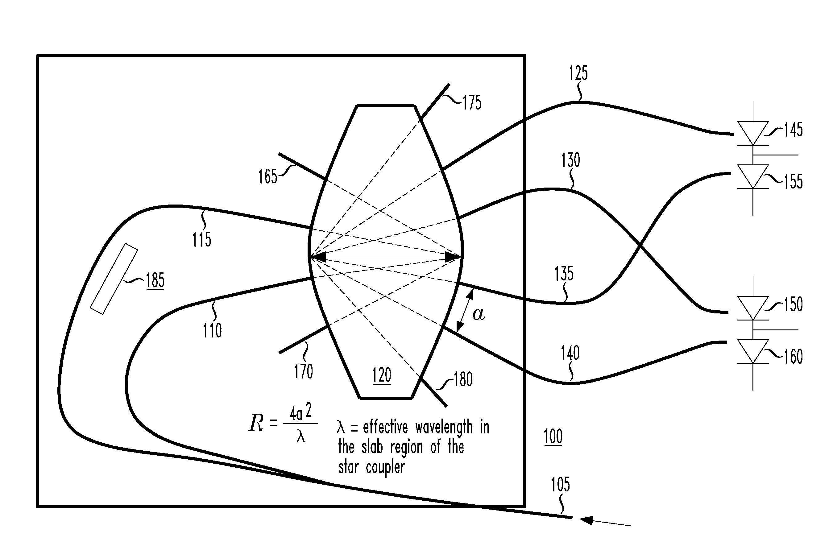
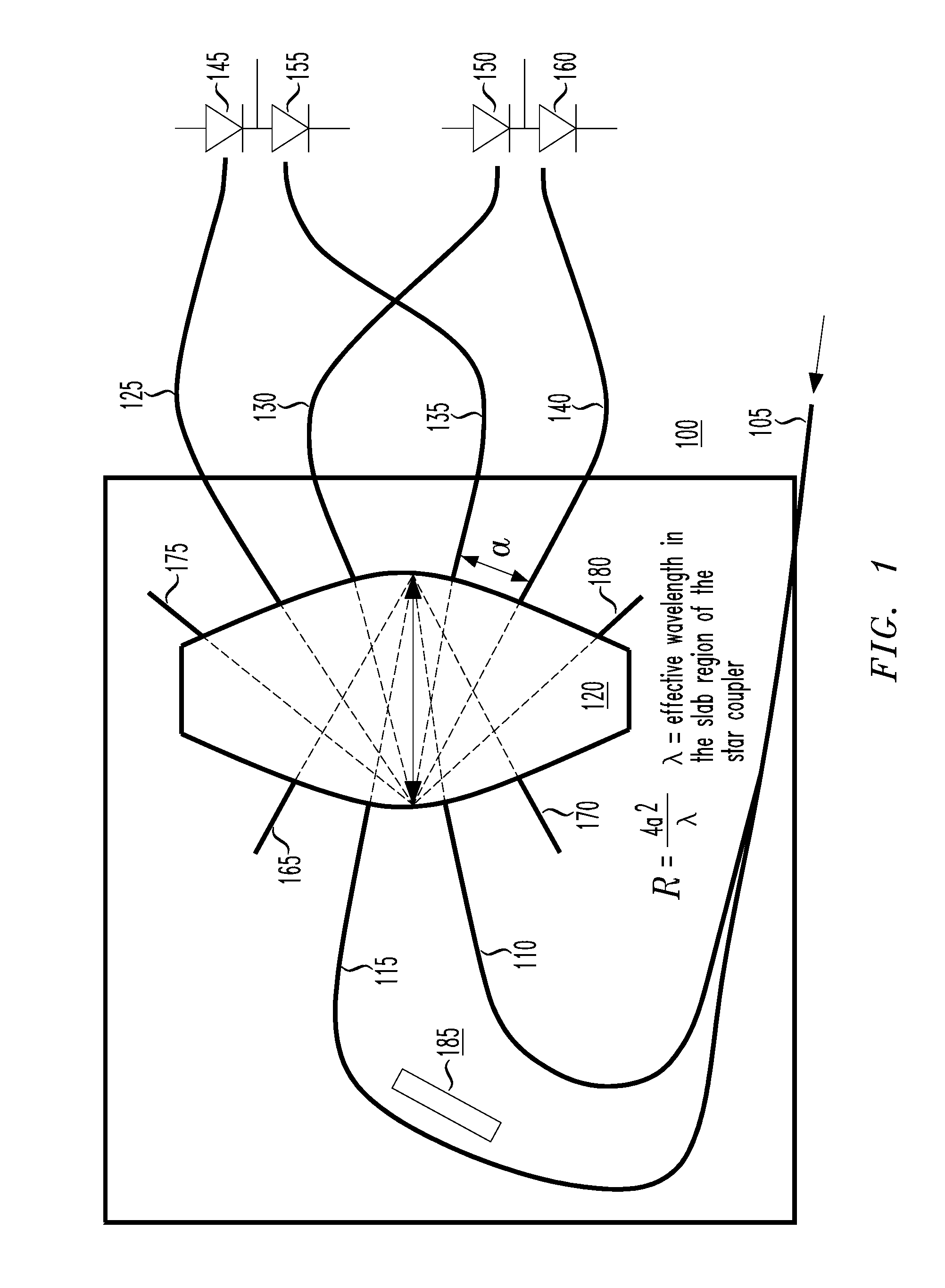
[0018]Referring initially to FIG. 1, illustrated is a block diagram of one embodiment of an optical DQPSK processor 100 constructed according to the principles of the present invention. The illustrated embodiment of the processor resides on a “silicon optical bench” (SiOB), which provides an optical substrate for supporting the various optical (and electrical) elements of the optical DQPSK processor 100. However, those skilled in the pertinent art will realize that other support apparatus may be used in lieu of SiOB.

[0019]The optical DQPSK processor 100 includes an optical port 105, which functions as an input port if the optical DQPSK processor 100 is a receiver and an output port if the optical DQPSK processor 100 is a transmitter. The optical port 105 is coupled to an optical waveguide 110 and a delay line 115 that is associated with the optical waveguide 110. (“Delay line” is defined broadly to include any structure that introduces a delay relative to the optical waveguide 110.)...


PUM


Abstract

An optical differential phase shift key (DPSK) receiver, a method of demodulating an optical DPSK modulated signal and an optical processor capable of operating as either a DPSK receiver or DPSK transmitter. In one embodiment, the DPSK receiver includes: (1) an optical waveguide and a delay line associated therewith configured to receive simultaneously an optical DPSK modulated signal, (2) a coupler having at least two inputs and at least four outputs, the at least two inputs configured to terminate the optical waveguide and the delay line, the delay line having a path length difference that delays the optical DPSK modulated signal by at least one timeslot relative to the optical waveguide and (3) photodetectors associated with the at least four outputs and configured to provide signals indicative of digital data contained in components of the optical DPSK modulated signal.

Description

TECHNICAL FIELD OF THE INVENTION[0001]The present invention is directed, in general, to optical communication systems and, more specifically, to an apparatus and method for receiving a quadrature differential phase shift key (DQPSK) modulated optical pulsetrain.BACKGROUND OF THE INVENTION[0002]Optical transmission systems built around optical fibers have become widely used for broadband communication of digital data. Differential phase shift keying (DPSK) is a modulation technique that is widely used for transforming the digital data into optical pulses carried by the optical fibers. DPSK's coding scheme assigns phase shifts between adjacent symbols to numbers (zero and one, since digital data is predominantly binary). Timeslots are defined, and an optical pulse is generated during each timeslot. The optical pulse in each timeslot is phase-shifted from the optical pulse in the preceding timeslot as a function of the coding scheme to transmit the digital data from a transmitter to a ...

Claims


Application Information

Patent Timeline
Patent Type & Authority Patents(United States)
IPC IPC(8): H04B10/06H04B10/158
CPCH04B10/677H04B10/69
Inventor DOERR, CHRISTOPHER R.GILL, DOUGLAS M.
Owner LUCENT TECH INC
Why Eureka
Try Eureka