Cap device

a technology of cap and spherical plate, which is applied in the direction of caps, liquid handling, applications, etc., can solve the problem of significant variation in the rotational torque in the closing direction

Active Publication Date: 2008-03-18
TOYODA GOSEI CO LTD
View PDF29 Cites 26 Cited by
  • Summary
  • Abstract
  • Description
  • Claims
  • Application Information

AI Technical Summary

Benefits of technology

[0008]The object of the invention is thus to provide a cap device having a torque mechanism that readily sets a rotational torque in a closing direction to a predetermined level.
[0013]In the cap device of this application, the torque mechanism has the second engagement element and the third engagement element that play different roles in the closing direction and in the opening direction. The second engagement element mainly covers the rotational torque in the closing direction, whereas the third engagement element mainly covers the rotational torque in the opening direction. The required rotational toque is thus readily set to the predetermined level by practically taking into account only the release of the engagement of the first engagement element with the second engagement element. The third engagement element mainly covers the rotational torque in the opening direction and prevents a significantly large load in the opening direction from being applied to the second engagement element. This arrangement desirably enhances the durability of the second engagement element. The structure of the invention does not require the engagement elements of an identical shape to fulfill the two contradictory parameters, that is, setting of the load for release of the engagement and setting of the mechanical strength. The structure of the invention uses the engagement elements of different shapes and thereby enables the load for release of the engagement and the mechanical strength to be set to respective adequate levels.
[0022]One preferable embodiment of the torque arm has a chamfered portion at its free end that comes into contact with the arm support member. The chamfered portion of the free end thus comes into contact with and is slid on the arm support member, when the torque arm is elastically deformed. This structure ensures smooth elastic deformation of the torque arms.

Problems solved by technology

Even slight change of the dimensions may result in a significant variation in rotational torque in the closing direction.

Method used


Image

  • Cap device
  • Cap device
  • Cap device

Examples


Embodiment Construction

[0041]One mode of carrying out the invention is discussed below as a preferred embodiment.

[0042](1) General Structure of Fuel Cap 10

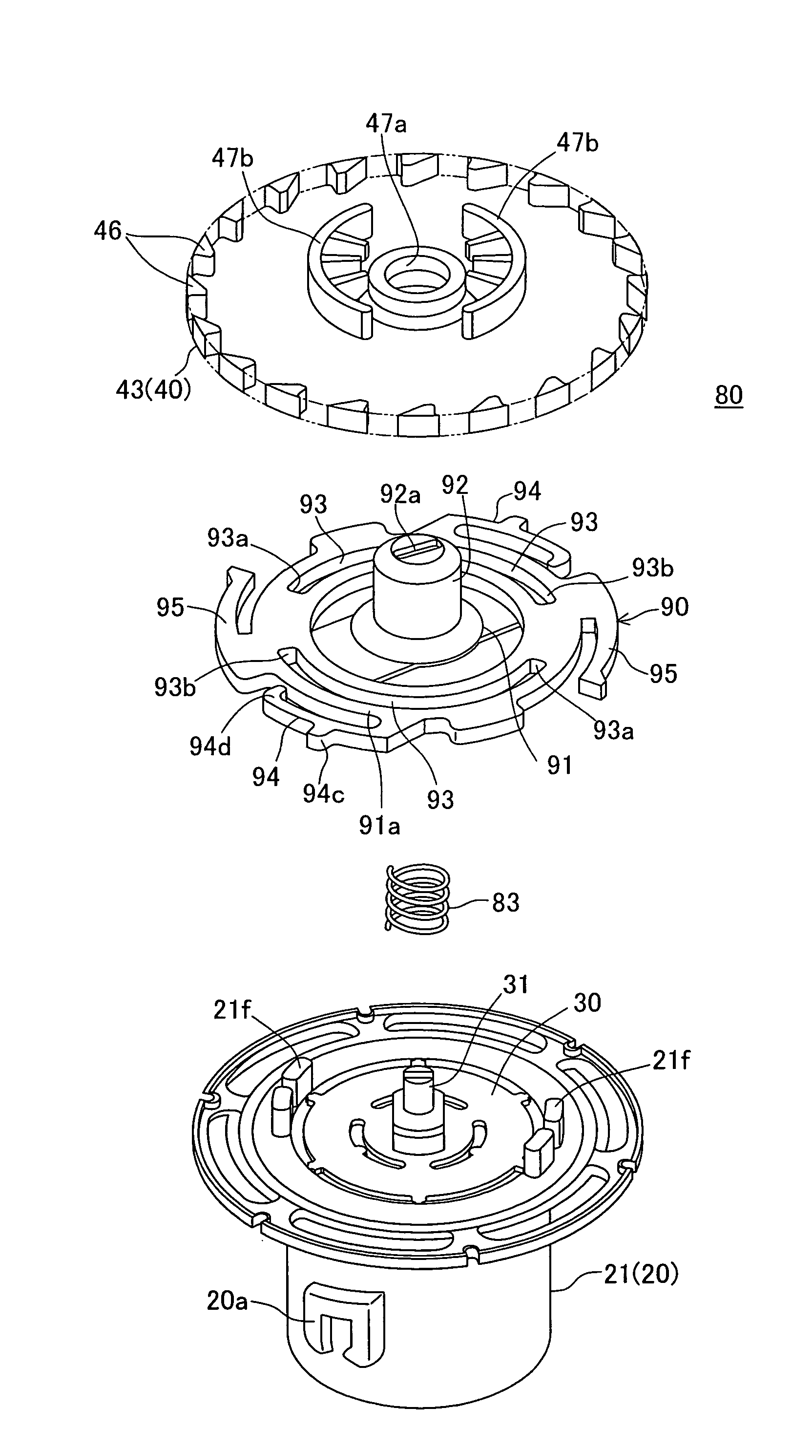
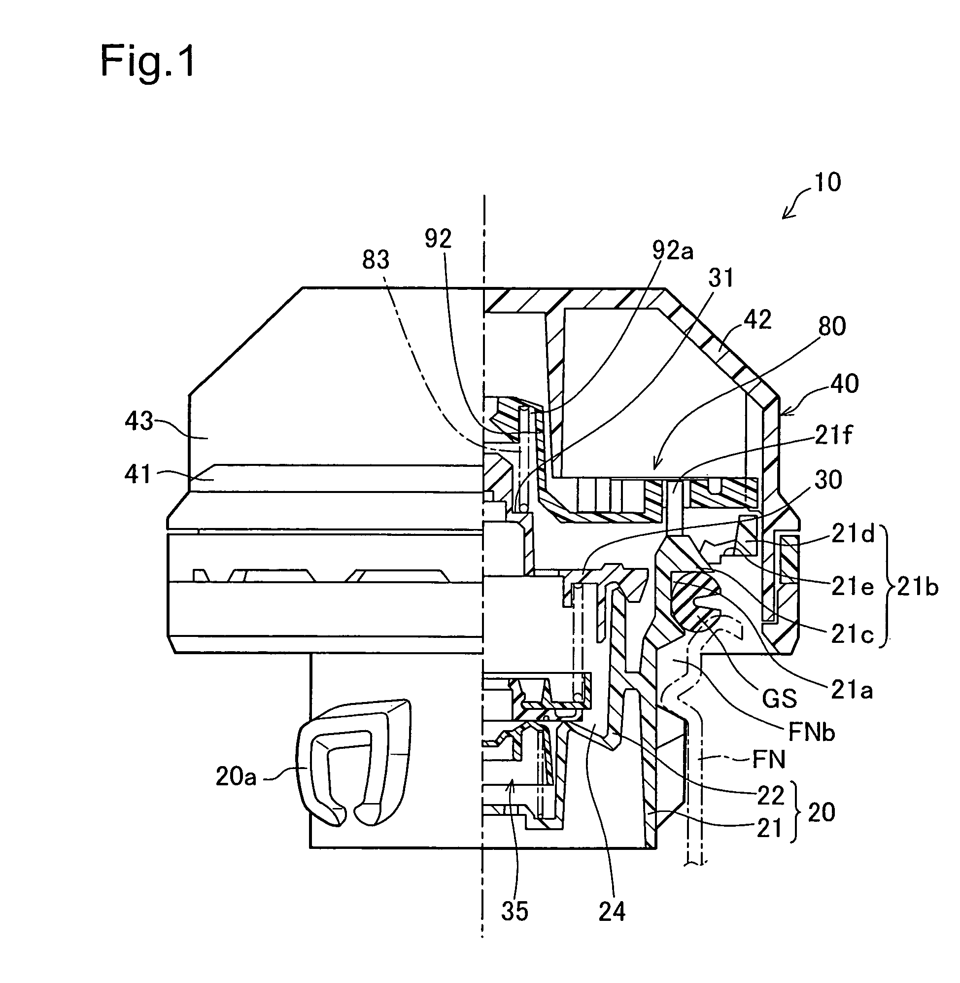
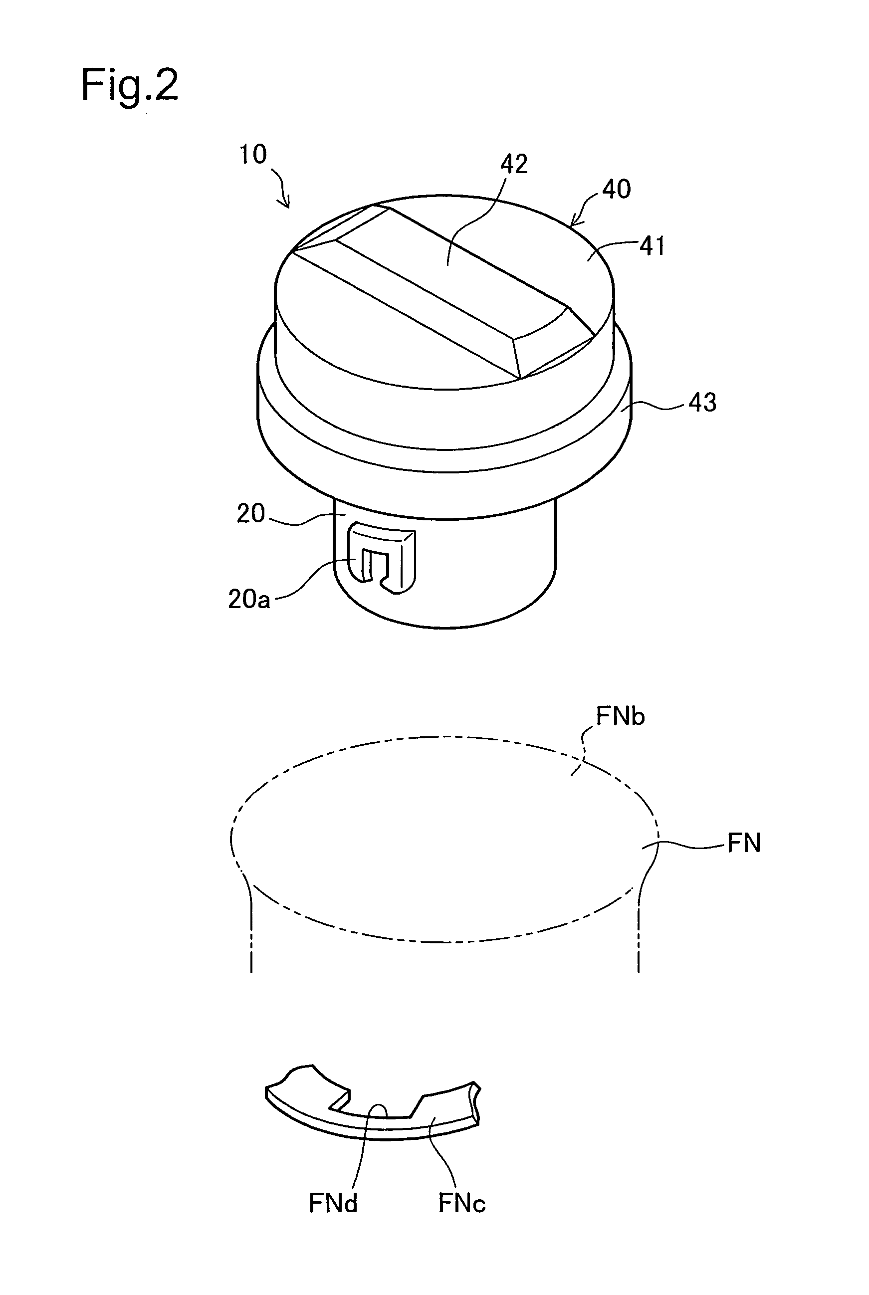
[0043]FIG. 1 is a half sectional view showing a fuel cap 10 (cap device) in one embodiment of the invention. The fuel cap 10 is attached to a filler neck FN having a fueling inlet FNb (tank opening) to feed a supply of fuel to a fuel tank (not shown). The fuel cap 10 has a casing main body 20 (closer) that is made of a synthetic resin material like polyacetal, a cover 40 that is mounted on the casing main body 20 and has a handle made of a synthetic resin material like nylon, an inner cover 30 that closes an upper opening of the casing main body 20 and forms a valve chest 24, a pressure regulating valve 35 that is received in the valve chest 24, a torque mechanism 80, and a gasket GS that is attached to the upper outer circumference of the casing main body 20 to seal the casing main body 20 against the filler neck FN.

[0044](2) Construction of Constituen...


PUM


Abstract

A fuel cap has a torque mechanism that transmits a rotational torque to a casing main body through engagement elements in response to rotation of a cover. When the rotational torque exceeds a predetermined level, the engagement is released to give a click. The first torque arm is constructed as a cantilever beam having a free end facing an arm support member across a preset gap. Under application of pressure, the first torque arm is deformed and transmits a rotational torque in the closing direction to the casing main body. This arrangement assures setting of the rotational torque of the torque mechanism to the predetermined level to apply a sufficient sealing stress to the fuel cap.

Description

[0001]This application claims the benefit of and priority from Japanese Application No. 2003-291205 filed Aug. 11, 2003 and No. 2003-291210 filed Aug. 11, 2003, the contents of which are incorporated herein by reference.BACKGROUND OF THE INVENTION[0002]1. Field of the Invention[0003]The present invention relates to a cap device having a torque mechanism for sealing a tank opening with a rotational torque of a predetermined level.[0004]2. Description of the Related Art[0005]A known fuel cap for an automobile fuel tank is disclosed in, for example, JP No. 2000-344266A. FIG. 17 is a decomposed perspective view showing a prior art torque mechanism 130 of a conventional fuel cap 100. The fuel cap 100 of FIG. 17 mainly has a casing main body 110, a cover 120 with a handle for rotational operations, and the torque mechanism 130. The torque mechanism 130 includes a handle engagement element 122 formed on the cover 120, a torque plate 140 having cantilevered torque arms 142 with torque engag...

Claims


Application Information

Patent Timeline
Patent Type & Authority Patents(United States)
IPC IPC(8): B65D41/04B60K15/04
CPCB60K15/0406B60K2015/0451Y10S220/32Y10S220/33
Inventor HAGANO, HIROYUKI
Owner TOYODA GOSEI CO LTD
Why Eureka
Try Eureka