Molded product assembly and fastener

a technology of product assembly and fastener, which is applied in the direction of threaded fasteners, screwdrivers, manufacturing tools, etc., can solve the problems of difficult attachment of resin molded products to the vehicle body panel, insufficient space, etc., and achieve the effect of smooth elasto-deformation

Active Publication Date: 2008-03-18
TOKAI KOGYO CO LTD
View PDF17 Cites 9 Cited by
  • Summary
  • Abstract
  • Description
  • Claims
  • Application Information

AI Technical Summary

Benefits of technology

[0010]Alternatively, the holding portion of the post and the portion to be held of the fastener maybe connected by a connecting member. With this constitution, the shapes of the holding portion of the post and the portion to be held of the fastener can be made simple, whereby there is an advantage that the structure of the mold for molding them is simplified, and the molding cost is reduced.
[0019]Also, the engagement portion of the fastener may have a substantially recessed shape so as to be fitted to a rim of the mounting hole of the body to be mounted. In this manner, the engagement portion of the fastener is engaged and held with the rim of the mounting hole of the body to be mounted in a state where it is prevented from slipping off in any of the front and back directions, whereby the molded product can be attached on the body to be mounted without the fastener getting rid of the mounting hole of the body to be mounted even by a method of mounting the fastener alone in the mounting hole of the body to be mounted beforehand and then mounting the molded product with the fastener.

Problems solved by technology

However, in a mounting structure of JP-A-9-226476, since the clip holder for engaging and holding the base portion of the mounting clip is formed on the back surface of the resin molded product, it is difficult to secure an enough space for providing the clip holder (base portion for the mounting clip) in the outside specifications in which the clearance between the back surface of the resin molded product and the vehicle body panel is narrow, resulting in a problem that the resin molded product is attached on the vehicle body panel with difficulty.

Method used


Image

  • Molded product assembly and fastener
  • Molded product assembly and fastener
  • Molded product assembly and fastener

Examples


first embodiment

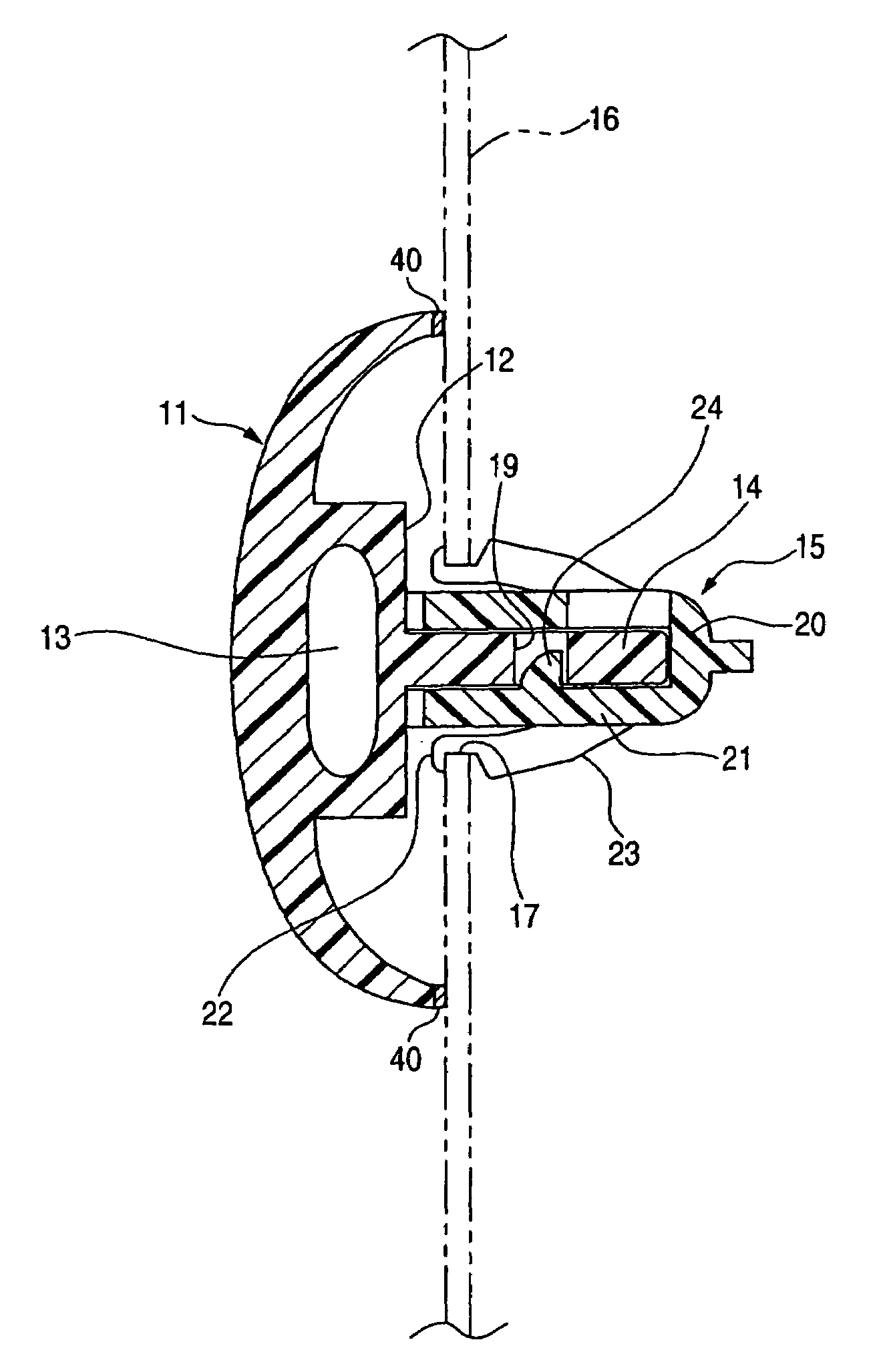
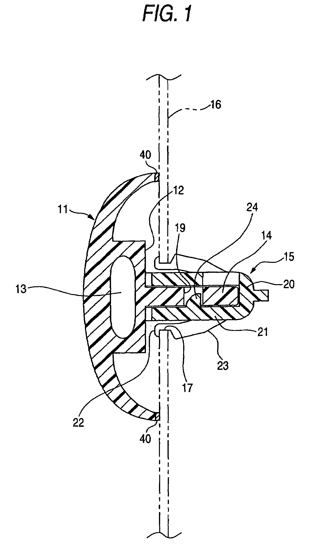
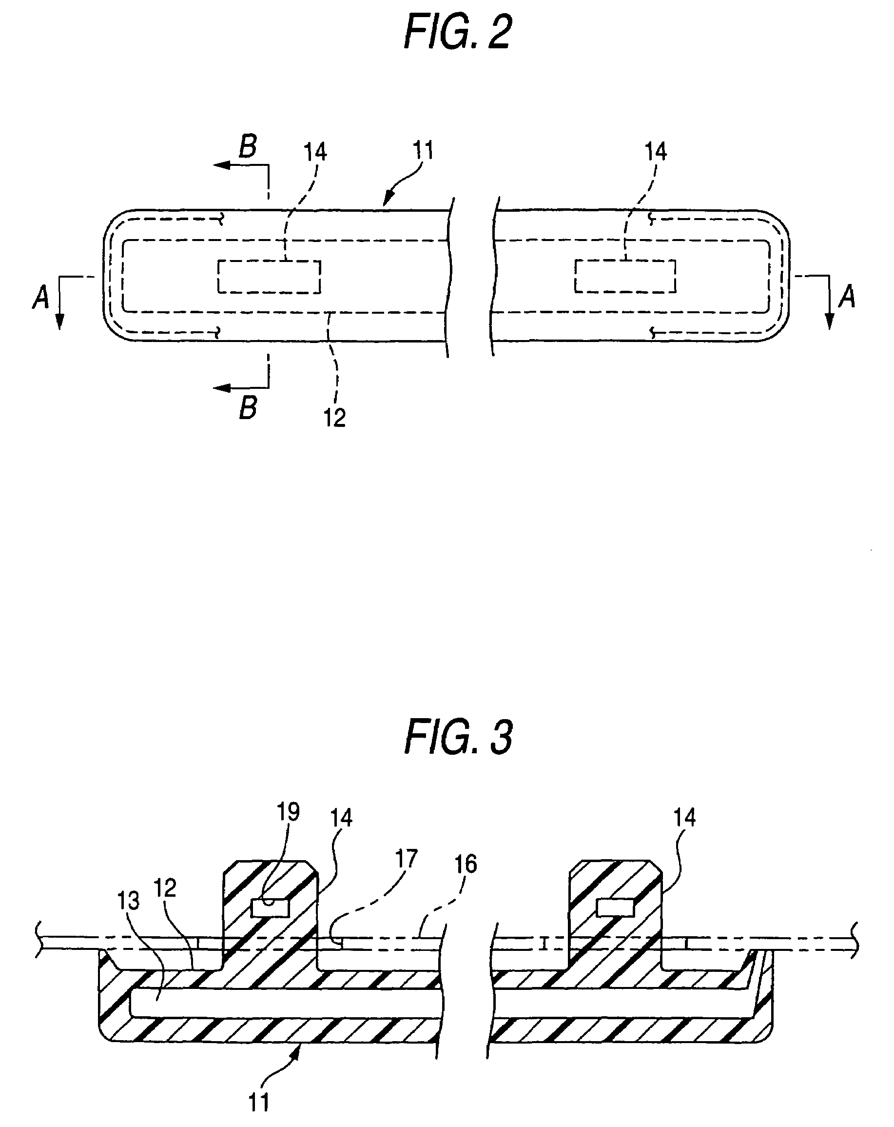
[0038]Referring to FIGS. 1 to 11, the invention will be described below. First of all, a schematic constitution of a side molding 11 (molded product) will be described using FIGS. 1 to 3. The long side molding 11 is an injection molded resin product having a longitudinal hollow inside and molded of thermoplastic resin such as PP (polypropylene) or ABS (acrylonitrile butadiene styrene) resin by gas assisted injection molding. This side molding 11 may be employed without making the surface treatment, or the surface treatment such as coating, painting and / or plating may be applied on the surface of the side molding 11 to improve the ornamentation or weather resistance. Alternatively, a colored film may be laminated and integrated on the surface of the side molding 11.

[0039]Also, a longitudinally extending raised portion 12 is integrally molded on a back surface side of the side molding 11, and a longitudinally extending hollow portion 13 is formed inside this raised portion 12. On a ba...

second embodiment

[0062]In the second embodiment, a hole or tapped hole 29 (holding portion) for fastening a screw 27 (fastener) is formed at a predetermined position (preferably at the top end) of the post 14, and correspondingly, a through hole for screw 28 (portion to be held) is formed at a predetermined position on the bottom portion 20 of the mounting clip 15. And the screw 27 such as a tapping screw inserted through the through hole for screw 28 on the bottom portion 20 is fastened into the hole 29 of the post 14, whereby the bottom portion 20 of the mounting clip 15 is connected and held to the post 14.

[0063]In the second embodiment as described above, since the post 14 and the bottom portion 20 of the mounting clip 15 are connected by the screw 27, there is no need for providing the engagement hole (or engagement recess) in the post 14 and the pinching portion 21, the shapes of the post 14 and the pinching portion 21 of the mounting clip 15 are made simple, whereby there is an advantage that...

third embodiment

[0066]In the third embodiment, a boss 30 (indicated by the two-dot chain line in FIG. 14) as a holding portion for holding the mounting clip 15 is formed at a predetermined position (e.g., top end portion) of the post 14, and correspondingly, a through hole 31 (portion to be held) for inserting the boss 30 is formed at a predetermined position on the bottom portion 20 of the mounting clip 15. In a process of mounting the mounting clip 15 in the post 14, the boss 30 of the post 14 is inserted into the through hole 31 of the bottom portion 20, and a concaved portion 33 formed at the top end of a heating head 32 is covered on the top end portion of the boss 30 and pressed in a state where a top end portion of the boss 30 is protruded from the through hole 31 of the bottom portion 20, as indicated by the two-dot chain line in FIG. 14. Thereby, the top end portion of the boss 30 is heated and softened, and squeezed like semi-sphere to cause plastic deformation, whereby the boss 30 is fir...


PUM

PropertyMeasurementUnit
widthaaaaaaaaaa
shapeaaaaaaaaaa
height sizeaaaaaaaaaa

Abstract

A molded product assembly includes a molded product being mountable to a body to be mounted having a mounting hole via a fastener. The molded product has a post projecting toward the mounting hole and disposed on a back surface of the molded product, at least a part of the post projecting through the mounting hole to a back surface side of the body to be mounted in mounting the molded product to the body to be mounted, and a holding portion disposed on the part of the post to hold the fastener. The fastener has a portion to be held that is held by the holding portion, and an elastic engagement leg being elastically deformable and having an engagement portion to be engaged with a peripheral edge of the mounting hole, the elastic engagement leg being located on the back surface side of the body to be mounted.

Description

BACKGROUND OF THE INVENTION[0001]1. Field of the Invention[0002]The present invention relates to a molded product assembly that can be mounted on a plate-shaped body to be mounted, and to a fastener.[0003]2. Description of the Related Art[0004]A resin molded product such as a body side molding for a vehicle is attached on the vehicle body panel by a mounting clip mounted on a back surface side of the resin molded product, as disclosed in JP-A-9-226476, for example. In JP-A-9-226476, a clip holder shaped like a U-character is integrally molded along a back surface of the resin molded product, a base portion of the mounting clip is fitted and engaged into this clip holder to mount the mounting clip on the back surface of the resin molded product, and a pair of elastic engagement pieces integrally molded on the back surface of the mounting clip are inserted and engaged into a mounting hole of the vehicle body panel to attach the resin molded product on the vehicle body panel.SUMMARY OF...

Claims


Application Information

Patent Timeline
Patent Type & Authority Patents(United States)
IPC IPC(8): B25G3/36E04G7/00F16B5/02B60R13/04B29C39/12B62D65/16F16B5/06F16B5/12F16B19/00
CPCB60R13/04Y10T403/7176Y10T403/7123Y10T24/309Y10S411/908Y10T24/42Y10S411/91Y10S411/903Y10T24/45995
Inventor KOBAYASHI, YOHSUKEWATO, YASUHIRO
Owner TOKAI KOGYO CO LTD
Why Eureka
Try Eureka