Transformer structure

a transformer and structure technology, applied in the field of transformers, can solve the problems of shortening the working life of the transformer, affecting the voltage resistance of the transformer, and the transformer may be burned out, so as to increase the leakage inductance and coupling effect, and increase the voltage resistance strength

Inactive Publication Date: 2008-03-18
TAIPEI MULTIPOWER ELECTRONICS
View PDF8 Cites 17 Cited by
  • Summary
  • Abstract
  • Description
  • Claims
  • Application Information

AI Technical Summary

Benefits of technology

[0011]The present invention has been accomplished under the circumstances in view. It is therefore the main object of the present invention to provide a transformer, which extends the creepage distance at the secondary side of each bobbin to prevent formation of a potential difference and to enhance the voltage resistance strength. It is another object of the present invention to provide a transformer, which utilizes induction between the ferrite core set and the secondary winding at each bobbin to increase the leakage inductance and the coupling effect.

Problems solved by technology

In this case, the transformer may be burned out.2. Bridging of the wire over the partition flanges A21 of the bobbin A may cause the secondary winding A2 to produce a potential difference that affects the voltage resistance of the transformer, thereby shortening the working life of the transformer.

Method used


Image

  • Transformer structure
  • Transformer structure
  • Transformer structure

Examples


Embodiment Construction

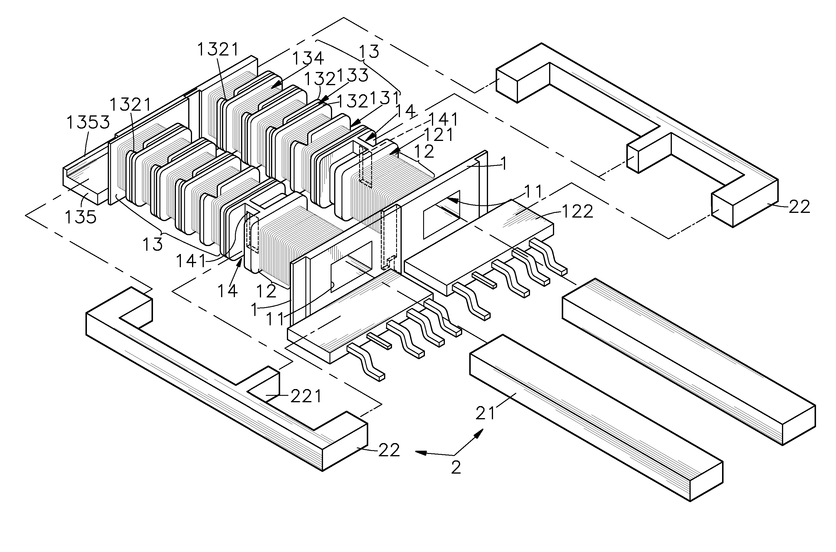
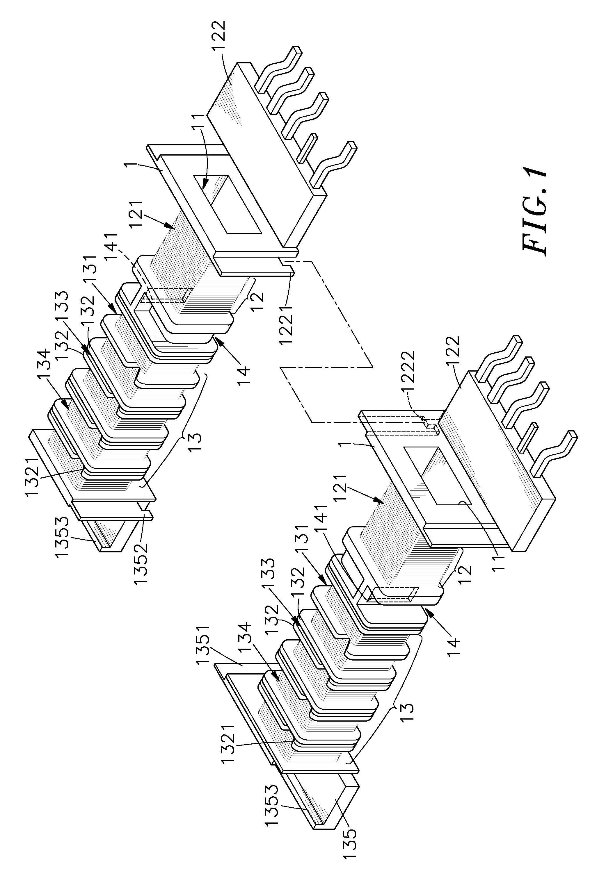
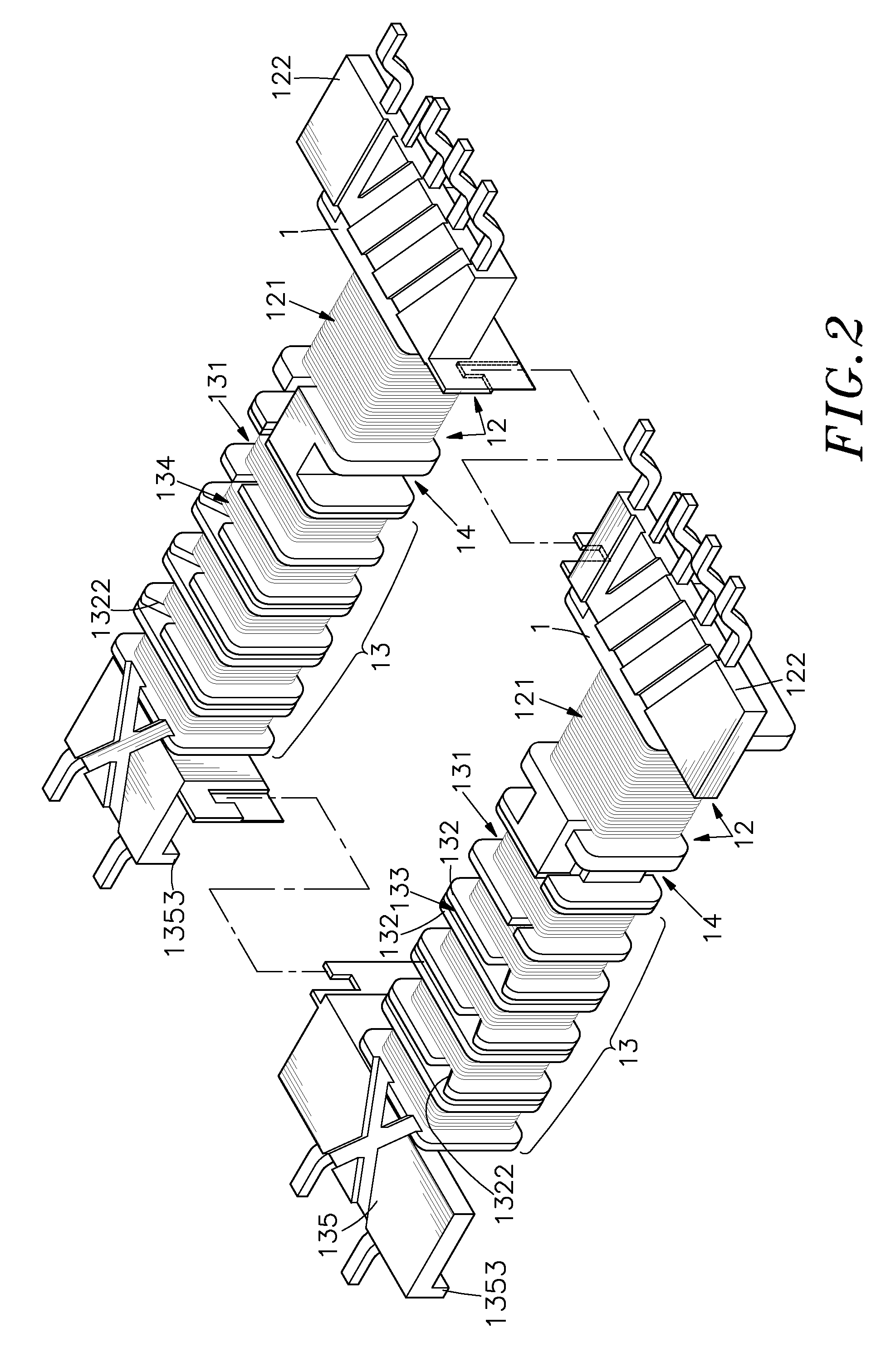
[0022]Referring to FIGS. 1˜4, a transformer in accordance with the present invention is shown comprised of two bobbins 1 and an ferrite core set 2.

[0023]The bobbins 1 are made out of an electrically insulative material. Each bobbin 1 comprises a center through hole 11 axially extending through its two distal ends, a primary side 12 and a secondary side 13 defined around the periphery, a partition space 14 defined around the periphery between the primary side 12 and the secondary side 13, a side through hole 141 cut through the periphery in communication between the partition space 14 and the center through hole 11, and two locating blocks, namely, a first locating block 122 and a second locating block 135 respectively and outwardly extending from the primary side 12 and the secondary side 13 in reversed directions. The secondary side 13 comprises a plurality of partition flanges 132 extending around the periphery of the bobbin 1 and arranged in parallel, a plurality of winding space...


PUM

PropertyMeasurementUnit
electrically insulativeaaaaaaaaaa
voltage resistance strengthaaaaaaaaaa
magnetic fieldaaaaaaaaaa

Abstract

A transformer is disclosed to include two bobbin, each bobbin having a primary side and a secondary side respectively holding a primary winding and a secondary winding, two first ferrite cores respectively inserted through the bobbins, two second ferrite cores arranged at two sides relative to the bobbins and abutted against each other, each second ferrite core having a middle protruding portion respectively inserted into the bobbins and to form with the first ferrite cores two independent magnetic loops. The secondary side of each bobbin has winding spaces for the winding of the wire for the secondary winding, partition flanges, vacant spaces defined between each two adjacent partition flanges, and top bridging notches and bottom bridging notches respectively formed on the partition flanges in such a manner that each vacant space has one side in communication with one top bridging notch and an opposite side in communication with one bottom bridging notch for guiding the wire of the secondary winding from one winding space to another through the vacant space without causing a potential difference.

Description

[0001]This application is a Continuation-In-Part of my patent application, Ser. No. 11 / 401,947, filed on Apr. 12, 2006.BACKGROUND OF THE INVENTION[0002]1. Field of the Invention[0003]The present invention relates to transformers and more particularly, to an improved transformer structure, which provides an extended creepage distance at the secondary side to prevent formation of a potential difference and to enhance the voltage resistance strength.[0004]2. Description of the Related Art[0005]FIG. 7 illustrates a conventional high frequency transformer, which comprises an electrically insulative bobbin A, and two ferrite cores B. The bobbin A has wound thereon a primary winding A1 and a secondary winding A2. The bobbin A further has a plurality of partition flanges A21 that divide the secondary winding A2 into multiple secondary winding portions A24. The partition flanges A21 have a respective notch A22 at the same side for the passing of the wire of the secondary winding A2. Further,...

Claims


Application Information

Patent Timeline
Patent Type & Authority Patents(United States)
IPC IPC(8): H01F5/00
CPCH01F27/325H01F27/326H01F38/10H01F3/12H01F2005/022H01F2005/043
Inventor YANG, CHING-SHENGWU, SU-HUAWANG, SHU-CHEN
Owner TAIPEI MULTIPOWER ELECTRONICS
Why Eureka
Try Eureka