Key unit with reinforcing plate

a technology of reinforcing plate and keypad, which is applied in the field of key units, can solve the problems of difficulty in applying automatic assembly, inability to precisely maintain gaps, and soft keys, and achieve the effects of improving the precision of the key top position, imparting rigidity to the keypad, and reducing the flexibility of design

Inactive Publication Date: 2008-03-25
SUNARROW CO LTD
View PDF24 Cites 31 Cited by
  • Summary
  • Abstract
  • Description
  • Claims
  • Application Information

AI Technical Summary

Benefits of technology

[0066]In the conventional key units, the portions to which a decoration can be applied (hereinafter, referred to simply as “decoration”) are limited to the top surface, the side surface, and the back surface of the key top. However, the present invention allows to introduce a new element to enable the decoration, which broadens the flexibility of design. Further, the present invention can impart rigidity to the keypad; bring the effects such as the shape stability, the suitability for automatic assembly, the improvement of precision of the key top position or the like to the key unit; and allow the reinforcing plate to serve also as a light-conducting plate, which is equivalent to the hard base key unit disclosed previously.

Problems solved by technology

However, the conventional rubber keypads are too soft and lack shape stability, which causes various disadvantages such as incapability of precisely maintaining gaps between key tops and difficulty for applying automatic assembly.
In particular, when a casing is provided with a key frame in order to maintain gaps between the keys, such a new disadvantage occurs that the key tops do not return due to interference with the key frame.
However, the role of the reinforcing plate in Patent Reference 1 only remains imparting rigidity to the keypads and serving also as a light-conducting plate, and no idea is recognized such that the reinforcing plate is positively utilized for a design element of equipment.

Method used


Image

  • Key unit with reinforcing plate
  • Key unit with reinforcing plate
  • Key unit with reinforcing plate

Examples


embodiment 1

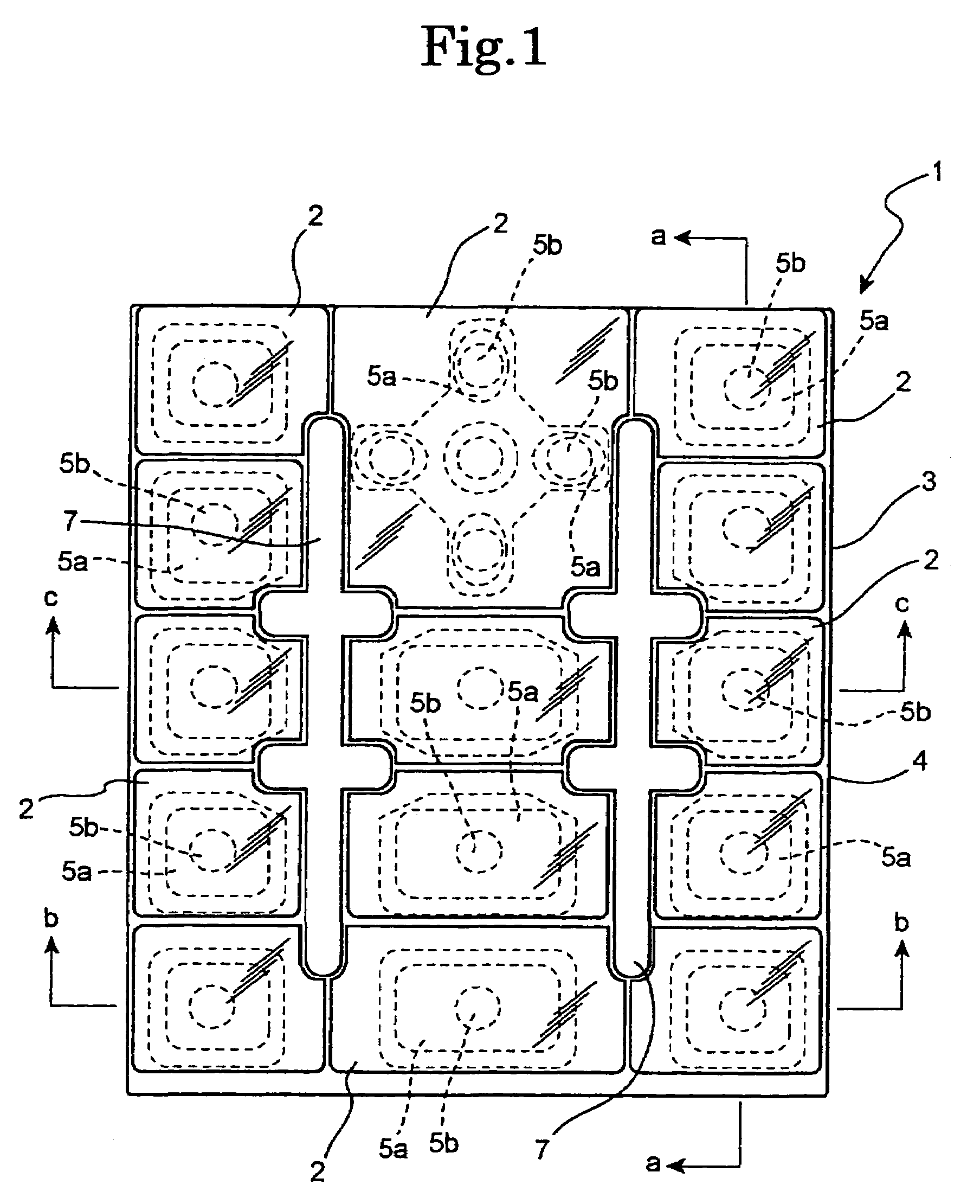
[0076]FIGS. 1 to 8 show Embodiment 1 of the key unit with metal reinforcing plate (hereinafter, referred to as merely “key unit”) of the present invention. The present Embodiment 1 sets forth that a part of the metal reinforcing plate is exposed, in the shape of two inequality symbols, between key clusters which constitute three columns as a whole.

[0077]A key unit 1 has key tops 2, 2, . . . , and a keypad 3 which are formed in desired shapes. The key top 2 is formed out of a hard resin which has excellent transparency such as PC(polycarbonate resin), PET (polyethylene terephthalate resin) or PMMA polymethylmethacrylate / acrylate resin) The keypad 3 comprises a reinforcing plate 4 made of a metal in the form of a plate as a whole, and a pad member 5 constituting a key operation part. That is, the keypad 3 referred to as in the present specification is a composite member made of the metal reinforcing plate 4 and the pad member 5 made of a rubber elastic body. It should be added that fo...

embodiment 2

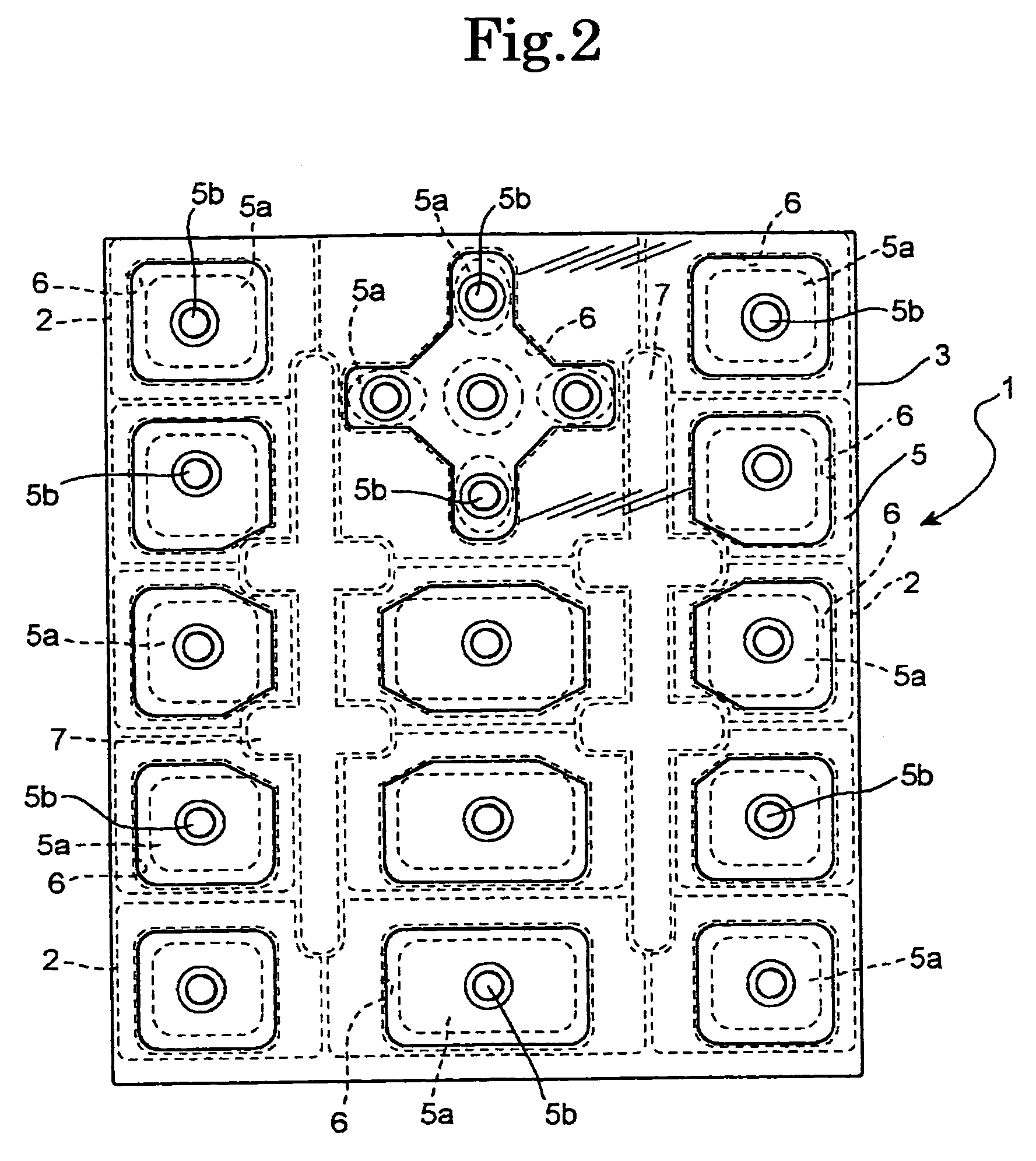
[0091]FIG. 10 is plan view showing a key unit 1B with metal reinforcing plate as Embodiment 2 of the present invention. The key unit 1B differs from the above-mentioned key unit 1 only in the shape and the number of the exposed part of the metal reinforcing plate 4. Therefore, an explanation is omitted by using the same symbol as the one used in the above-mentioned Embodiments for the parts which have the configuration similar to the above-mentioned Embodiments. That is, the key unit 1B is an example in which, as shown in FIG. 10, five locations between the keys of the reinforcing plate 4 are exposed through the space between the key tops 2, 2, . . . as the exposed parts 7, 7, . . . , so that each exposed part 7 is formed into an appropriate shape such as a star shape or a dumpling shape, or into an arbitrary letter string of “ABCDE.”

[0092]Thus, in the key unit 1B, it is possible to freely set the number and the shape of the exposed parts 7, 7, of the metal reinforcing plate 4. In a...

embodiment 3

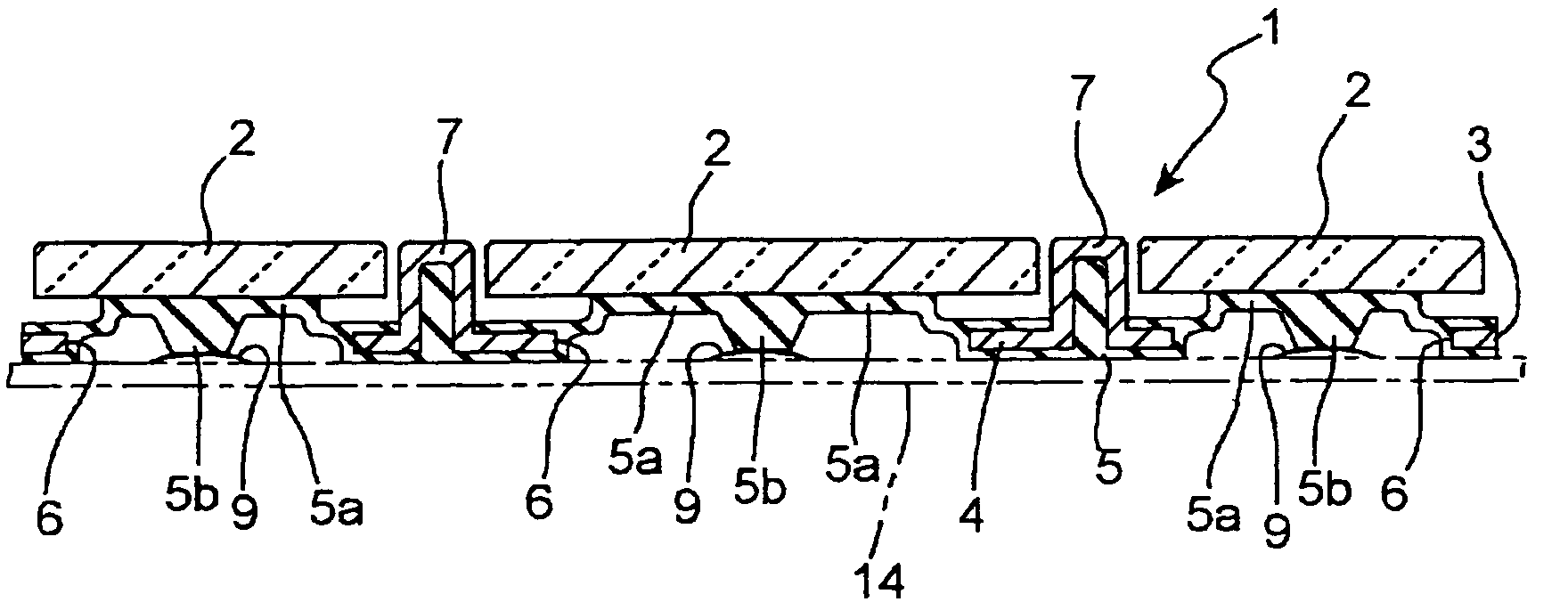
[0093]FIGS. 11 and 12 show a key unit 1C with metal reinforcing plate as Embodiment 3. The key unit 1C differs from each of the above-mentioned Embodiments in the shape of the keypad 3, and show an example in which the exposed part 7 of the reinforcing plate 4 is entirely exposed through the space between each of the key tops 2, i.e., the exposed part 7 is formed integrally so as to surround the perimeter of the key tops 2, 2, . . . entirely. That is, in the reinforcing plate 4, apertures 6, 6, . . . in which the pad members 5, 5 . . . are arranged, and other parts except one part of the perimeter of the opening edge of the apertures 6, 6, . . . are protruded to the one side as the exposed part 7. The apertures 6, 6, . . . and parts 14, 14, on which the key tops 2, 2, . . . of the reinforcing plate 4 constituted by a part of the perimeter of its opening edge is placed have relatively concave shapes. Further, FIG. 13 shows one example 15 of a portable phone into which the above-menti...


PUM


Abstract

The object of the present invention is to utilize a reinforcing plate formed out of a metal or a hard resin introduced into a key unit in order to overcome the weak point that conventional rubber keypads are too soft and lack shape stability, as a design element of equipment including a key unit into which the plate is incorporated.For example, a part of metal reinforcing plate 4 is positively exposed to a position which can be seen from the outside of key unit 1, and various decorations are applied to the exposed part 7 so as to allow it to function as a decorated component. As a location where the reinforcing plate is exposed, there can be cited a part between each key on the key face or an annular part which encircles a plurality of key clusters. A mode may be considered in which the part of the exposed reinforcing plate 4 surrounds each individual key top 2 like a key frame, so as to substitute a key frame which has been conventionally realized by the equipment casing. The shape of the exposed part of the reinforcing plate 4 is arbitrary. For example, letters, symbols, or the like may be formed.

Description

[0001]This application is a U.S. National Phase Application under 35 USC 371 of International Application PCT / JP2005 / 003856 filed Mar. 7, 2005.TECHNICAL FIELD [0002]The present invention relates to a key unit for use in mobile equipment such as portable phones and personal digital assistants (PDA), in particular, to a key unit with a reinforcing plate which imparts shape retention-ability to a rubber keypad using a hard plate material.BACKGROUND ART[0003]A key unit is a type of components constituting mobile equipment such as portable phones and personal digital assistants (PDA), and a unit in which a multiplicity of keys (push buttons) for switch operation are assembled and arrayed on a surface of a single sheet. A single key comprises a key top made of a hard resin adhered to the surface of flexible rubber keypads such as various rubbers including a silicone rubber or thermoplastic elastomers, and a switch-pressing projection (what is called “pressing element”) formed on the back ...

Claims


Application Information

Patent Timeline
Patent Type & Authority Patents(United States)
IPC IPC(8): H01H13/70H01H13/02H01H13/14H01H13/704
CPCH01H13/704H01H2209/006H01H2209/01H01H2221/012H01H2229/048H01H13/705
Inventor IOHARA, YUICHI
Owner SUNARROW CO LTD
Why Eureka
Try Eureka