Light-emitting module

a technology of light-emitting modules and modules, which is applied in the direction of lighting support devices, semiconductor/solid-state device details, coupling device connections, etc., can solve the problems of light engine however not providing a means for protecting leds from the environment, each module requires a complicated housing,

Active Publication Date: 2008-03-25
SIGNIFY HLDG BV
View PDF16 Cites 178 Cited by
  • Summary
  • Abstract
  • Description
  • Claims
  • Application Information

AI Technical Summary

Benefits of technology

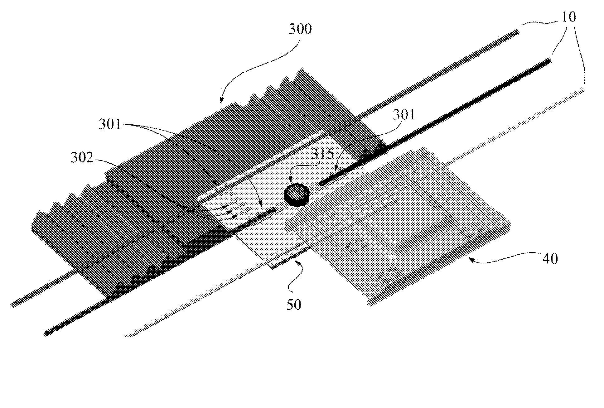
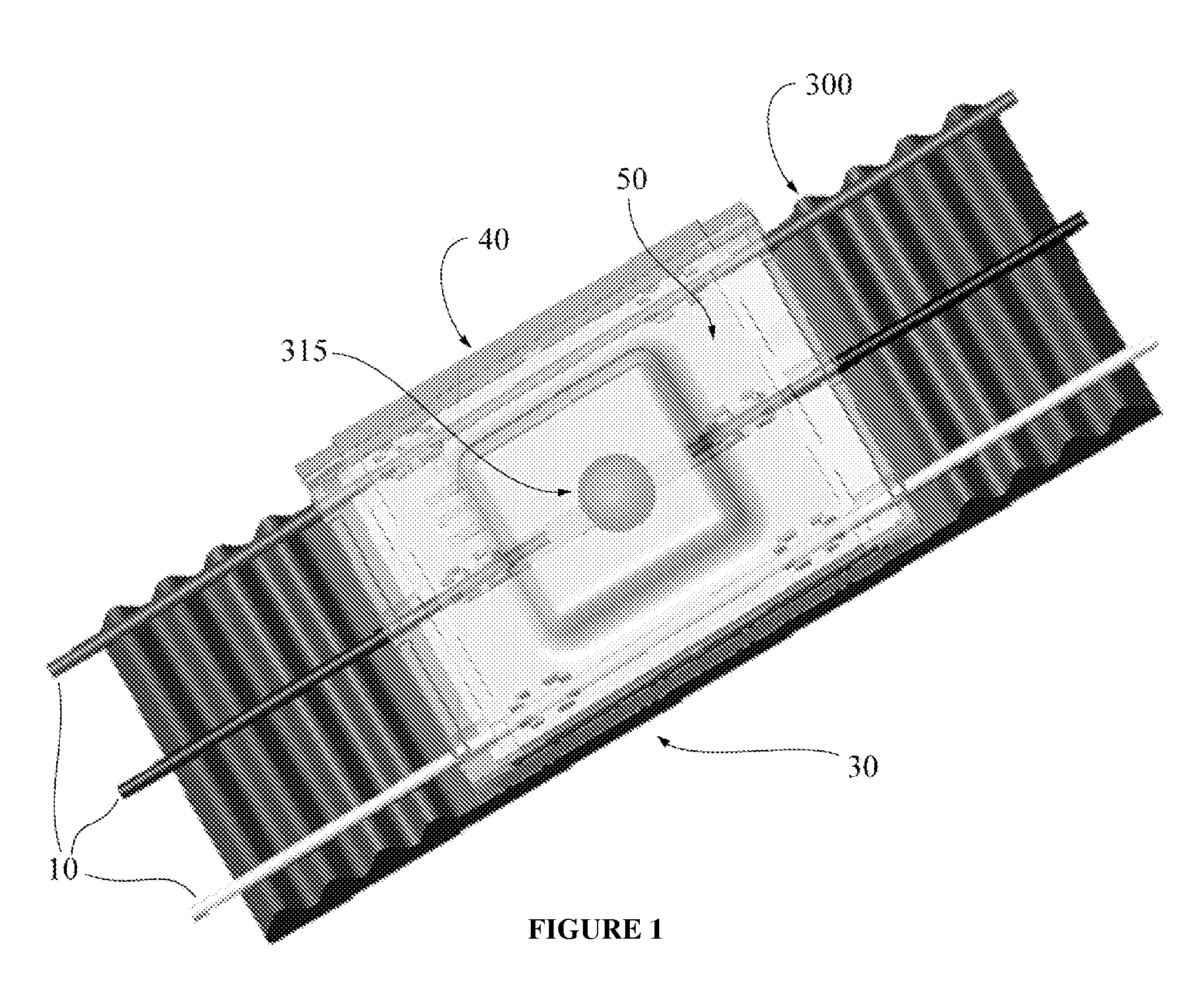
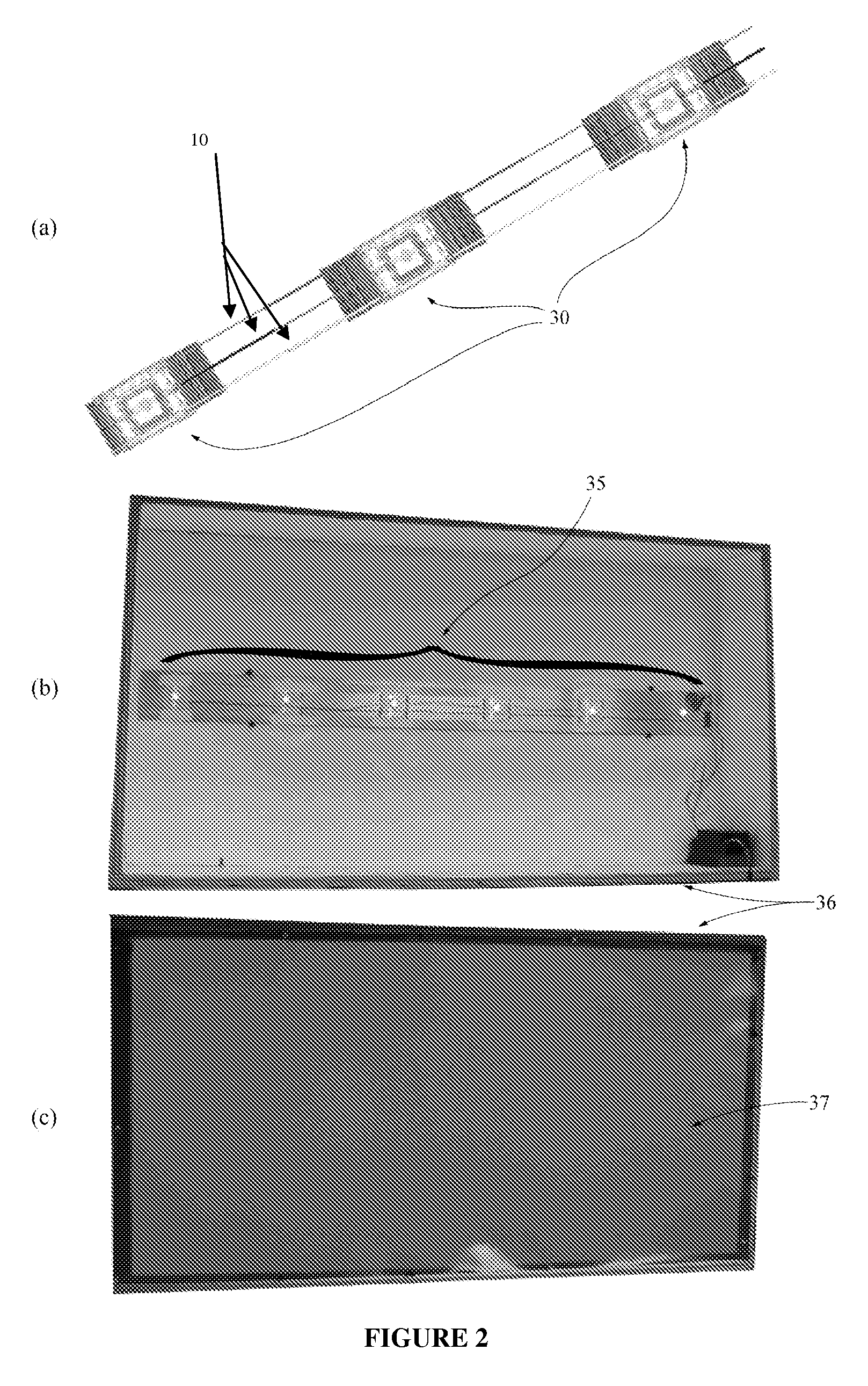
[0014]An object of the present invention is to provide a light-emitting module. In accordance with an aspect of the present invention, there is provided a light-emitting module comprising: a thermally conductive substrate having one or more light-emitting elements thermally connected thereto, the substrate configured to operatively couple a source of power to the one or more light-emitting elements, thereby providing a means for activation of the one or more light-emitting elements; a heat dissipation element thermally coupled to the thermally conductive substrate; and a housing element including fastening means for detachably coupling the housing element to the heat dissipation element, said substrate being enclosed between the heat dissipation element and said housing element, said housing element including a transparent region enabling transmission of light emitted by the one or more light-emitting elements therethrough.

Problems solved by technology

This lighting device however, does not provide a means for dissipating heat generated by the LED elements.
The light engine however does not provide a means for protecting the LED from the environment.
For this configuration, however, each module requires a complicated housing that provides mechanical and electrical functionality.
A problem with this configuration is that soldering and potentially cutting of the leads are required which can be time consuming and cumbersome during installation.
In addition, a predetermined wiring length and the use of the thermally conductive extrusion to mechanically mount the module can require extra parts which can make the overall design more complicated and potentially less cost effective.
While there are many designs of light-emitting modules that facilitate heat sinking with relatively easy wiring, the prior art designs may not be simple enough to improve manufacturing, simplify assembly, and provide ease of maintenance.

Method used


Image

  • Light-emitting module
  • Light-emitting module
  • Light-emitting module

Examples


Embodiment Construction

Definitions

[0025]The term “light-emitting element” is used to define any device that emits radiation in any region or combination of regions of the electromagnetic spectrum for example, the visible region, infrared and / or ultraviolet region, when activated by applying a potential difference across it or passing a current through it, for example. Therefore a light-emitting element can have monochromatic, quasi-monochromatic, polychromatic or broadband spectral emission characteristics. Examples of light-emitting elements include semiconductor, organic, or polymer / polymeric light-emitting diodes, optically pumped phosphor coated light-emitting diodes, optically pumped nano-crystal light-emitting diodes or any other similar light-emitting devices as would be readily understood by a worker skilled in the art. Furthermore, the term light-emitting element is used to define the specific device that emits the radiation, for example a LED die, and can equally be used to define a combination ...


PUM


Abstract

The light-emitting module according to the present invention comprises a heat dissipation element, a substrate for example a metal core printed circuit board (MCPCB), or FR4 board which is coupled to one or more light-emitting elements and provides a means for operative connection of the light-emitting elements to a source of power. The substrate is positioned such that it is thermally coupled to the heat dissipation element. The light-emitting module further comprises a housing element which matingly connects with the heat dissipation element, wherein the housing element may further comprise an optical element integrated therein for manipulation of the light generated by the one or more light-emitting elements.

Description

FIELD OF THE INVENTION[0001]The present invention pertains to the field of lighting systems and in particular to a light-emitting module with versatile electromechanical mounting, connecting, and assembly capabilities.BACKGROUND[0002]Advances in the development and improvements of the luminous flux of light-emitting devices such as semiconductor, organic or polymer light-emitting diodes (LEDs) have made these devices suitable for use in general illumination applications, including architectural, entertainment, and roadway lighting, for example. As such, LEDs are becoming increasingly competitive with light sources such as incandescent, fluorescent, and high-intensity discharge lamps.[0003]LEDs offer a number of advantages and are generally chosen for their ruggedness, long lifetime, high efficiency, low voltage requirements, and the possibility to control the colour and intensity of the emitted light independently. They provide an improvement over delicate gas discharge lamp, incand...

Claims


Application Information

Patent Timeline
Patent Type & Authority Patents(United States)
IPC IPC(8): H01L29/22H01L29/24H01L33/00H01L33/48H01L33/62H01L33/64
CPCF21V29/763F21V15/01F21V19/003F21V21/002F21V29/004H01L33/483H01L33/62H01L33/648H01R13/50H01R13/6658H01R13/7175F21V29/74F21V5/00F21V5/045F21V21/08F21V31/04F21Y2101/02H01L33/645H01L51/529H01R25/14F21V29/006H01R12/675H01L2224/48091F21V5/002H01L2924/00014F21Y2115/10H10K50/87
Inventor MATHESON, GEORGE E.
Owner SIGNIFY HLDG BV
Why Eureka
Try Eureka