Grease cover for heat dissipating apparatus

a heat dissipation apparatus and grease cover technology, applied in the direction of electrical apparatus construction details, light and heating apparatus, basic electric elements, etc., can solve the problems of contaminating surrounding objects or being contaminated by dust or foreign particles, deteriorating the appearance of sinks, and contaminating electronic components

Inactive Publication Date: 2008-03-25
FU ZHUN PRECISION IND SHENZHEN +1
View PDF28 Cites 16 Cited by
  • Summary
  • Abstract
  • Description
  • Claims
  • Application Information

AI Technical Summary

Benefits of technology

[0005]The present invention relates to a grease protecting apparatus. According to a preferred embodiment of the present invention, a grease cover adapted for protecting thermal grease spread on a bottom surface of a heat sink includes a base wall, a plurality of sidewalls, a protecting space, a holding space, and two projections. The sidewalls are disposed around the base wall, and defining the protecting space with the base wall. The protecting space is adapted for accommodating the thermal grease. The holding space is defined at a top portion of the protecting space, adapted for engagingly receiving the heat sink therein. The projections extend from two opposite ones of the sidewalls of the grease cover toward a center thereof. A top surface of each of the projections spaces a distance from the base wall, adapted for supporting the bottom surface of the heat sink to enable the grease away from the base wall when the heat sink is received in the holding space.

Problems solved by technology

Since the thermal grease is not solid at ambient temperature, it may contaminate surrounding articles or be contaminated by dust or foreign particles before the heat sink is assembled to the electronic component.
The remained adhesive on the heat sink deteriorates the appearance of the heat sink and sometimes may contaminate electronic components when the user is not careful in handling the heat sink.

Method used


Image

  • Grease cover for heat dissipating apparatus
  • Grease cover for heat dissipating apparatus
  • Grease cover for heat dissipating apparatus

Examples


second embodiment

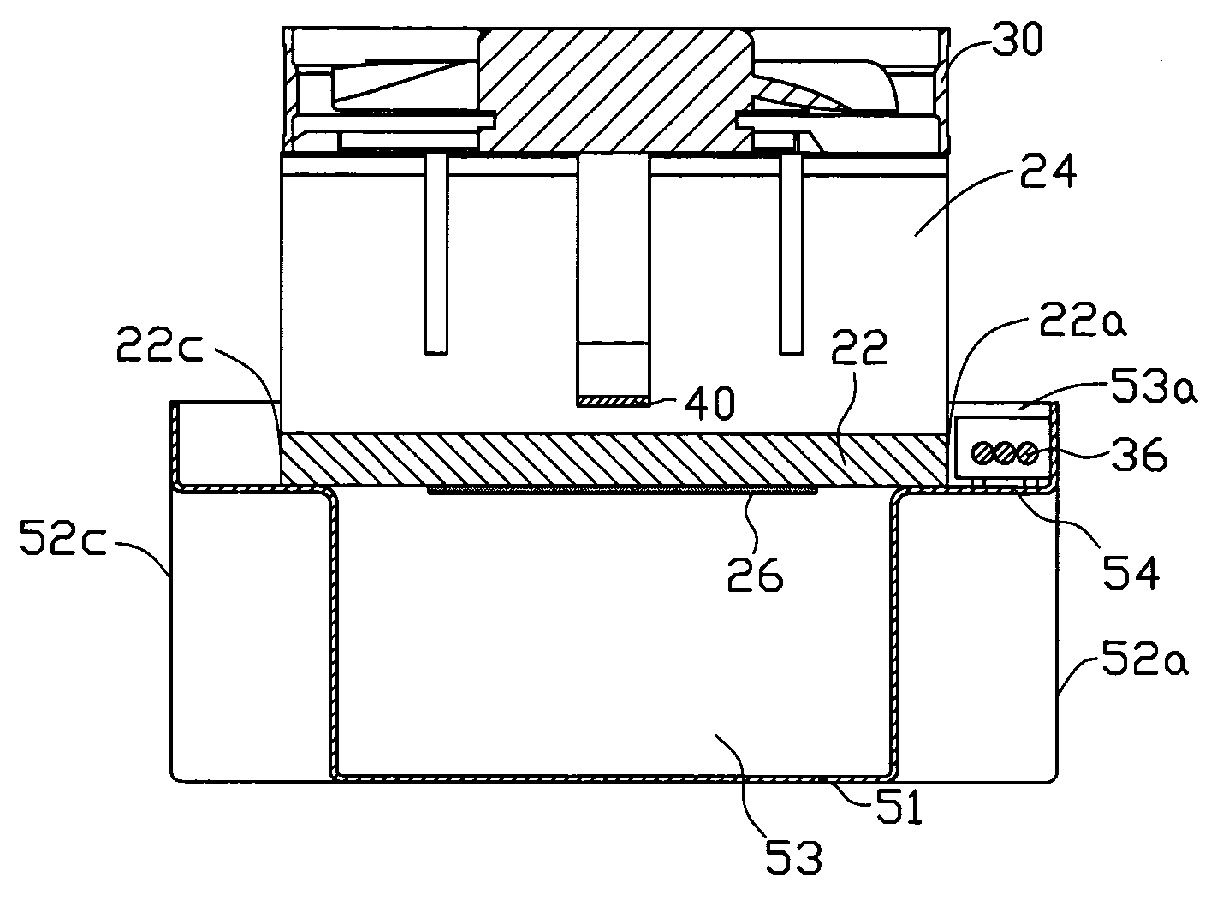
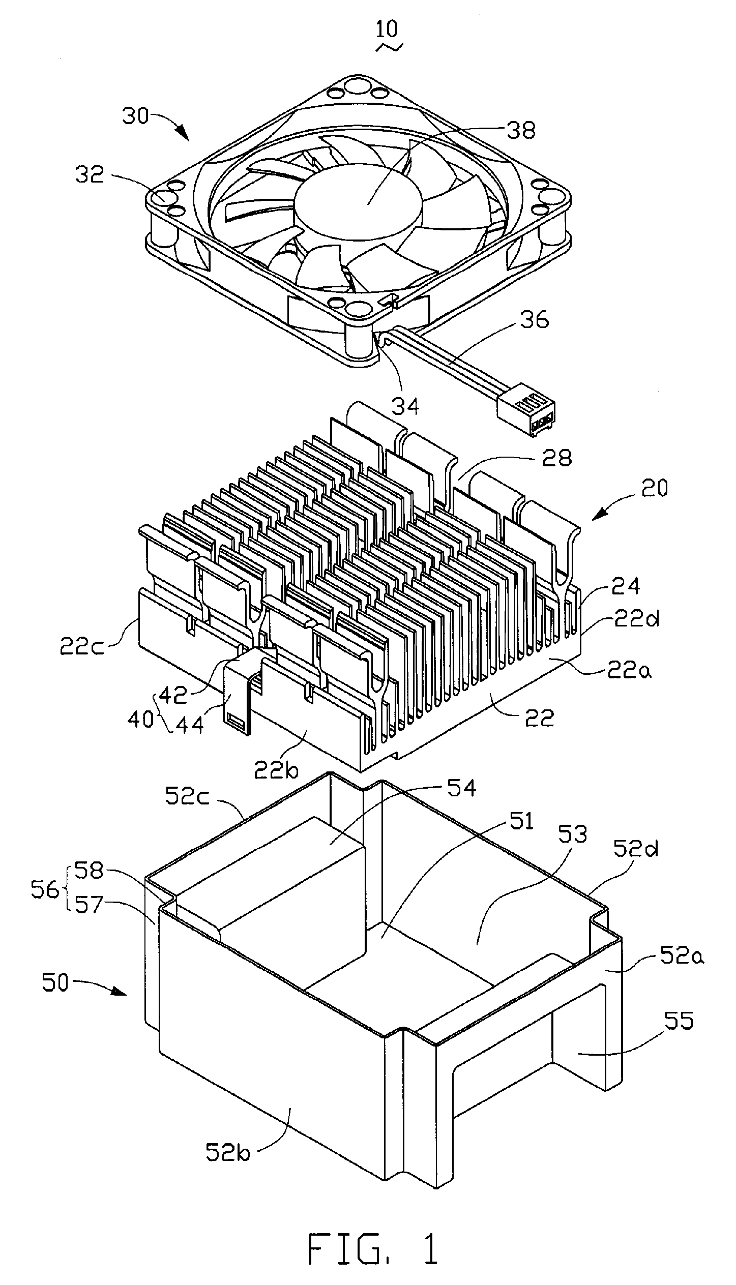
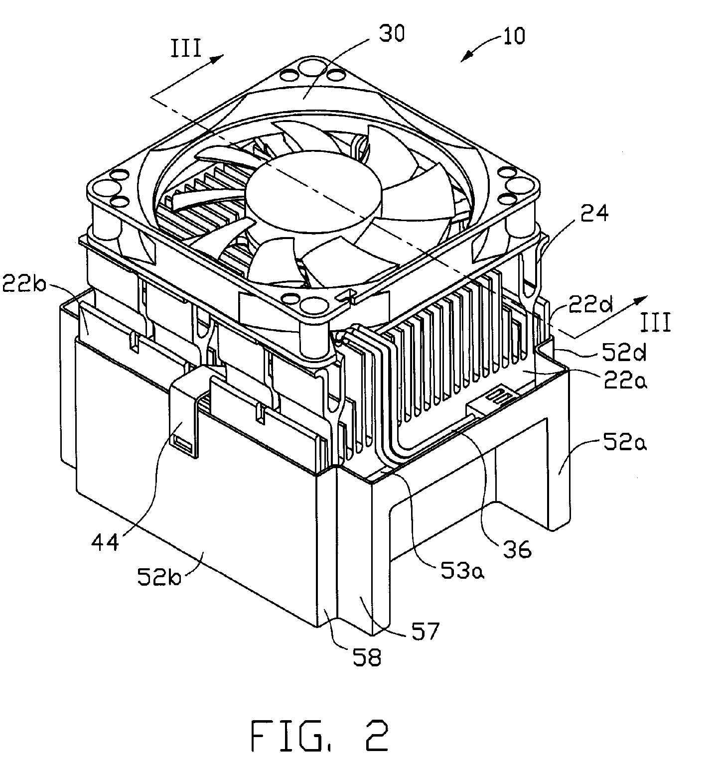
[0021]Referring to FIG. 6, a grease cover 50′ according to the present invention is shown. In this modified embodiment, each of the other two sidewalls 52b, 52d of the grease cover 50′ also extends a projection 54′ toward the central portion of protecting space 53′of the grease cover 50′. When the heat sink 20 is mounted to the grease cover 50′ the heat sink 20 is supported by top surfaces of the projections 54′, in addition to the top surfaces of the projections 54 of the grease cover 50′. Therefore, the heat sink 20 can be more stably mounted in the grease cover 50′.

[0022]Referring to FIG. 7, a grease cover 50″ according to a third embodiment of the present invention is shown. The difference between this embodiment and the second embodiment is in that the grease cover 50″ further includes another abutting portion 56″ at each of four corners thereof. The abutting portions 56″ connect the four abutting portions 56 to the sidewalls 52b, 52d. According to this embodiment, the heat sin...

first embodiment

[0023]In a further alternative embodiment, although it is not shown in the drawings, it can be easily obtained by those skilled in the art by modifying the first embodiment by canceling the two abutting portions 56 adjacent to the sidewall 52c of the grease cover 50, thereby making the side 22c of the heat sink 20 directly abut against the sidewall 52c of the grease cover 50. Furthermore, the projections 54 may extend from the two opposite sidewalls 52a, 52c, and space a distance with the base wall 51 of the grease cover 50.


PUM


Abstract

A grease cover (50) for protecting grease spread on a bottom surface of a heat sink (20) includes a base wall (51), a plurality of sidewalls (52a, 52b, 52c, 52d), a protecting space (53) between the base wall and the sidewalls, a holding space in an upper portion of the protecting space, and two projections (54). The protecting space is for accommodating the grease. The holding space is for receiving the heat sink therein. The projections extend from two opposite sidewalls of the grease cover. A top surface of each of the projections spaces a distance from the base wall, for supporting the bottom surface of the heat sink to enable the grease away from the base wall, when the heat sink is received in the holding space.

Description

FIELD OF THE INVENTION[0001]The present invention relates generally to a grease cover, and particularly to a grease cover for a heat dissipating apparatus to separate thermal grease spread on the heat dissipating apparatus from surrounding articles.DESCRIPTION OF RELATED ART[0002]A layer of thermal grease is usually spread on a bottom surface of a heat sink to improve heat conductivity between the heat sink and an electronic heat-generating component. The heat generated by the electronic component causes the thermal grease to become more liquid, enabling the thermal grease to fill in air gaps formed between the heat sink and the electronic component, thereby improving heat conductivity between the heat sink and the electronic component.[0003]Since the thermal grease is not solid at ambient temperature, it may contaminate surrounding articles or be contaminated by dust or foreign particles before the heat sink is assembled to the electronic component. To avoid the contamination, a gr...

Claims


Application Information

Patent Timeline
Patent Type & Authority Patents(United States)
IPC IPC(8): H05K7/20
CPCH01L23/4093H01L23/467H01L2924/0002Y10S165/905H01L2924/00
Inventor SHENG, JIAN-QINGCHEN, CHIN-LUNG
Owner FU ZHUN PRECISION IND SHENZHEN
Why Eureka
Try Eureka