Method and apparatus for relaying a wireless signal

a wireless signal and wireless technology, applied in the field of wireless signal relaying methods and apparatuses, can solve the problems of noise amplification and require very stringent transmit to receive isolation

Active Publication Date: 2008-03-25
MALIKIE INNOVATIONS LTD
View PDF2 Cites 91 Cited by
  • Summary
  • Abstract
  • Description
  • Claims
  • Application Information

AI Technical Summary

Benefits of technology

[0037]In some embodiments, each SPST switch comprises switching elements selected from a grou

Problems solved by technology

The available analogue relays require dual RF transceiver chains, and in-band relays which suffer from noi

Method used


Image

  • Method and apparatus for relaying a wireless signal
  • Method and apparatus for relaying a wireless signal
  • Method and apparatus for relaying a wireless signal

Examples


Embodiment Construction

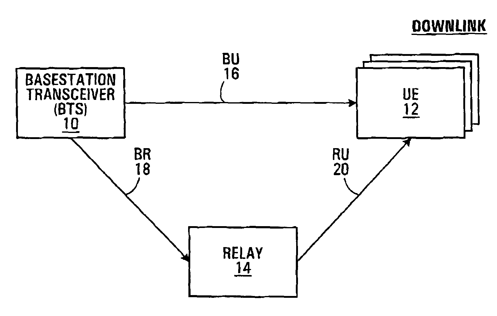
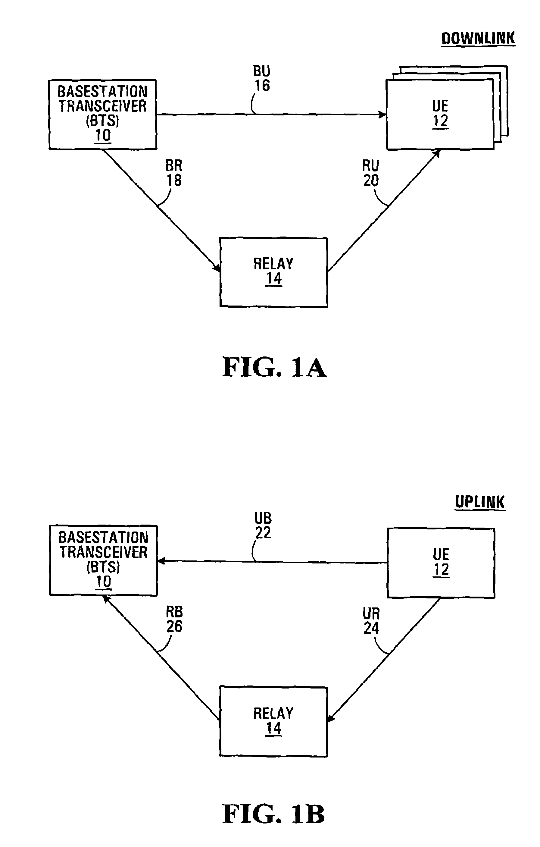
[0049]Embodiments of the invention will now be described with reference to FIGS. 1A and 1B. Each of these figures shows a BTS (Base Station Transceiver) 10, a wireless relay 14, and a user equipment (UE) 12. The BTS 10 might for example be a normal cell site base station, and would be capable of delivering the full services to the UE 12, whatever those services might be. In a given network, typically there would be a collection of BTSs 10. The UE 12 is a wireless terminal which may be fixed or mobile and is obtaining service via the BTS 10. Typically, there would be a large number of UEs 12 within the coverage area of the BTS 10. Relay 14 is a node within the coverage area of BTS 10 which implements a relaying function to extend the coverage area beyond the normal range of the BTS 10. In FIG. 1A, the potential connectivities between the nodes 10,12,14 in respect of downlink communications from the BTS 10 to the UE 12 are shown. There is the possibility for direct communications from...


PUM


Abstract

Systems and Methods are provided for relaying wireless signals bi-directionally between user equipment (UE) and base station transceivers (BTS). Various slot types are defined during which a relay node takes on the personality of either the UE or the BTS. In order to implement the relay node with a single transceiver chain, a first switching matrix is used to switch high band and low band RF bandpass filters between receive and transmit paths, and a second switching matrix is used to switch two frequency sources between the receive and transmit path. In this way, a single receive path can function both in the UE and BTS personality, as can the single transmit path.

Description

FIELD OF THE INVENTION[0001]The invention relates to methods and apparatus for relaying wireless signals.BACKGROUND OF THE INVENTION[0002]Cellular wireless systems typically employ a base station at the center of each cell which provides service to users within that cell. In order to increase the converge area of a given base station, it has been proposed to introduce a relay function within the conventional cellular network. This will allow the extension of the network to a multi-hop network topology in which some mobile users would communicate with the network via the relay function and then the base station.[0003]The conventional relay technology that is available includes analogue relays and digital relays both of which come in the form of external band relays. The available analogue relays require dual RF transceiver chains, and in-band relays which suffer from noise amplification and feedback isolation problems and requires very stringent transmit to receive isolation. The ava...

Claims


Application Information

Patent Timeline
IPC IPC(8): H04B7/15
CPCH04B7/15542H04B7/2606
Inventor ZHU, PEIYINGTONG, WENJIA, MINGWU, JIANMINGWU, SHIQUANBEAUDIN, STEVE
Owner MALIKIE INNOVATIONS LTD
Why Eureka
Try Eureka