Rate dependent transmission gain control for WLAN systems

a transmission gain control and rate-dependent technology, applied in the field of wireless local area network (wlan) transmitters, can solve the problems of low signal-to-noise ratio, increased error rate at the receiver, and decreased signal quality

Active Publication Date: 2008-03-25
ADVANCED MICRO DEVICES INC
View PDF12 Cites 17 Cited by
  • Summary
  • Abstract
  • Description
  • Claims
  • Application Information

AI Technical Summary

Benefits of technology

[0019]An improved WLAN transmission technique is provided that allows for optimum transmission gain selection in a WLAN multi-mode environment.

Problems solved by technology

As there are non-linearities in the power amplifier 185, the signal quality decreases when the output power is increased since there may occur severe signal distortions.
This may lead to a situation where the signal-to-noise ratio is low but signal demodulation and decoding nevertheless leads to higher error rates at the receiver because of the reduced signal quality.
It is therefore often found difficult to decide on the compromise between signal-to-noise ratio and signal quality.
This may lead to situations where a WLAN receiver cannot successfully demodulate and decode a signal either because of too much noise (i.e. too weak data signals) or because of distorted signals.

Method used


Image

  • Rate dependent transmission gain control for WLAN systems
  • Rate dependent transmission gain control for WLAN systems
  • Rate dependent transmission gain control for WLAN systems

Examples


Embodiment Construction

[0027]The illustrative embodiments of the present invention will be described with reference to the figure drawings wherein like elements and structures are indicated by like reference numbers.

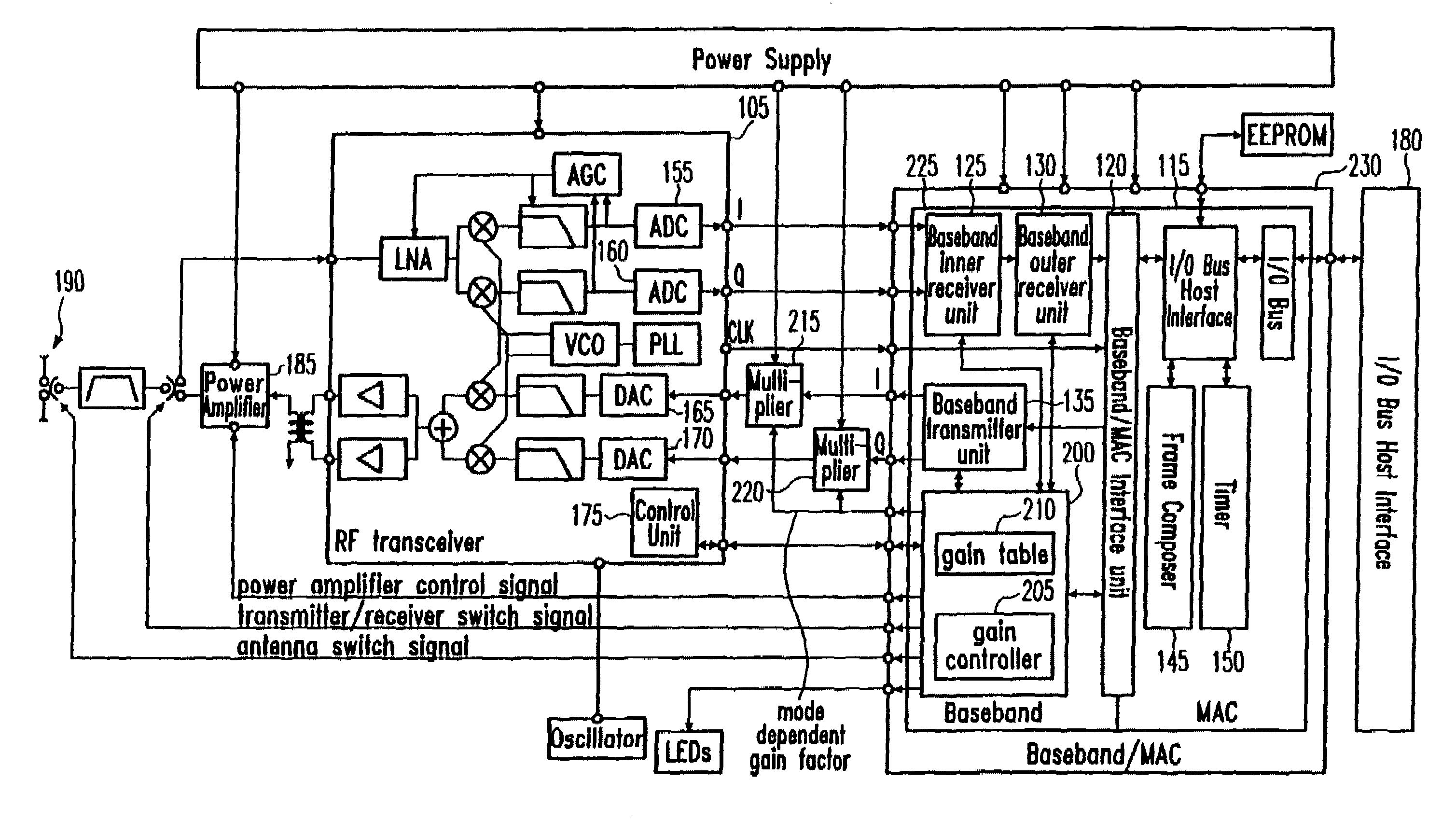
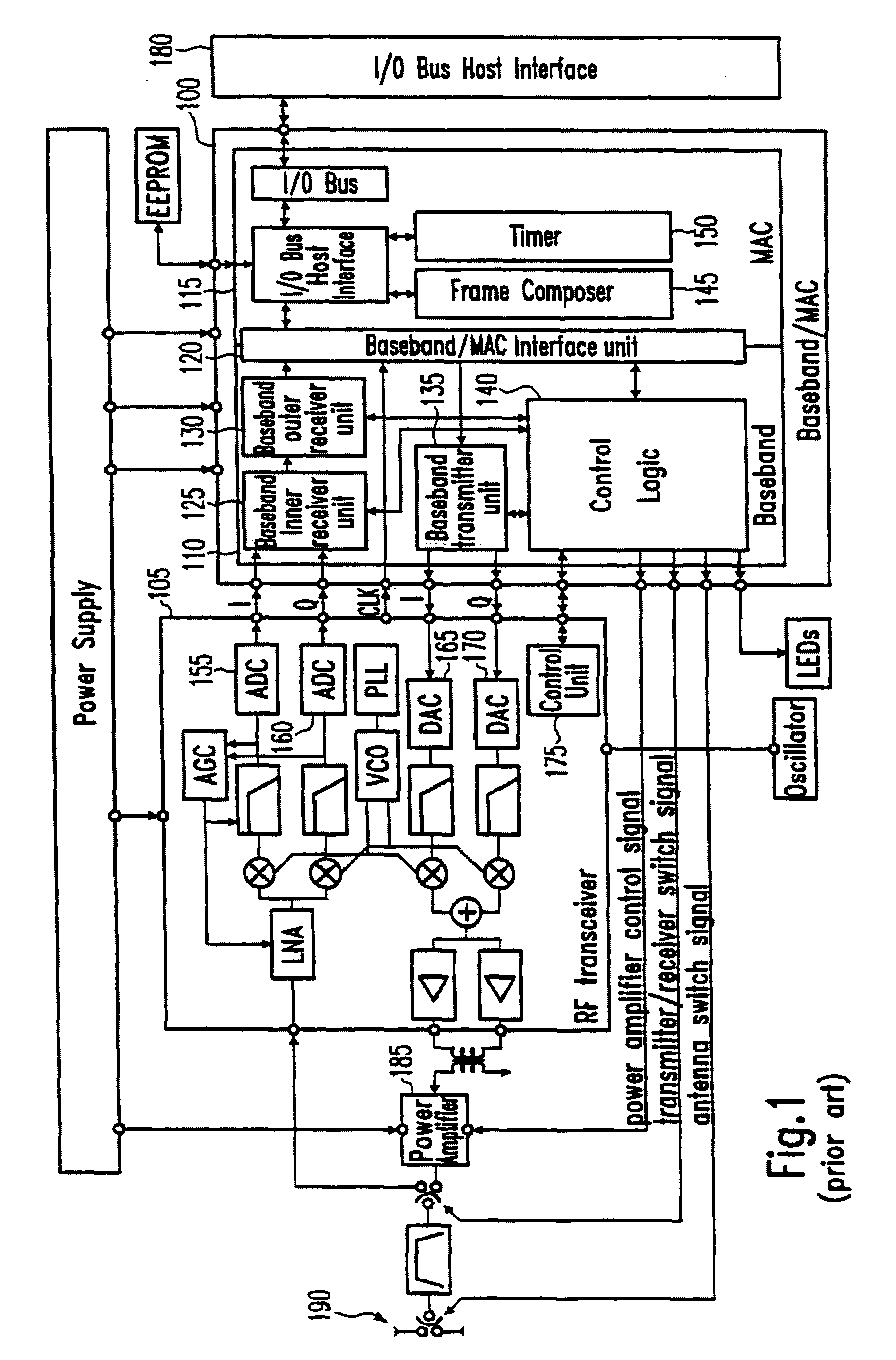
[0028]Referring now to FIG. 2, a WLAN transmitter device according to an embodiment is depicted. Comparing the block diagram of FIG. 2 with that of FIG. 1, it is apparent that the baseband / MAC unit 230 comprises in its baseband section 225 a control logic 200 which comprises a gain controller 205 and a gain table 210. Further, two multipliers 215, 220 are provided between the baseband / MAC unit 230 and the RF transceiver 105. The multipliers 215, 220 multiply the digital in-phase (I) and quadrature-phase (Q) output signals of the baseband transmitter unit 135 with a mode (or rate) dependent gain factor that is provided by the control logic 140. The multiplication results are then provided to the digital-to-analog converters 165, 170 of the RF transceiver 105 to be converted to analog signals fo...


PUM


Abstract

A WLAN (Wireless Local Area Network) transmission technique is provided where data is transmitted in two or more different transmission modes at different transmission rates. A transmission gain is determined to be applied when transmitting data. The transmission gain is determined to be transmission mode dependent such that the transmission gain in a first transmission mode is greater than the transmission gain in a second transmission mode if the transmission rate in the first transmission mode is lower than the transmission rate in the second transmission mode.

Description

BACKGROUND OF THE INVENTION[0001]1. Field of the Invention[0002]The invention generally relates to WLAN (Wireless Local Area Network) transmitters and corresponding integrated circuit chips and methods, and in particular to WLAN transmission techniques where data is transmitted in two or more different transmission modes.[0003]2. Description of the Related Art[0004]A wireless local area network is a flexible data communications system implemented as an extension to or as an alternative for, a wired LAN. Using radio frequency or infrared technology, wireless LANs transmit and receive data over the air, minimizing the need for wired connections. Thus, wireless LANs combine data connectivity with user mobility.[0005]Most WLAN systems use spread spectrum technology, a wide-band radio frequency technique developed for use in reliable and secure communication systems. The spread spectrum technology is designed to trade-off bandwidth efficiency for reliability, integrity and security. Two ...

Claims


Application Information

Patent Timeline
Patent Type & Authority Patents(United States)
IPC IPC(8): H04Q7/20H04B1/04H04B7/005H04J11/00H04L12/28H04W88/06
CPCH04B1/04H04B2001/0416H04W88/06
Inventor HANUSCH, THOMASBEYER, SASCHASCHMIDT, MICHAEL
Owner ADVANCED MICRO DEVICES INC
Why Eureka
Try Eureka