Electromagnetic controlled fuel injection apparatus with poppet valve

a fuel injection apparatus and electric motor technology, applied in the direction of valve operating means/release devices, functional valve types, machines/engines, etc., can solve the problems of affecting the safe and stable operation of the engine, affecting the safety of the engine, and irregular fuel injection at the start and end of injection, so as to achieve effective prevention or restraint of the poppet valve, easy handling, and easy access to the inside space

Active Publication Date: 2008-04-01
MITSUBISHI HEAVY IND ENGINE & TURBOCHARGER LTD
View PDF18 Cites 8 Cited by
  • Summary
  • Abstract
  • Description
  • Claims
  • Application Information

AI Technical Summary

Benefits of technology

[0013]The object of the present invention is to provide an electromagnetic controlled fuel injection apparatus with a poppet valve of which the beginning and end of fuel injection is controlled by the reciprocation of the poppet valve. Inertia force and friction force due to the reciprocating motion of the poppet valve should be utilized effectively to suppress the bounce of the poppet valve.
[0014]To attain the object, the present invention proposes an electromagnetic controlled fuel injection apparatus with a poppet valve. The beginning and end of fuel injection is controlled by opening and closing a passage connecting to a fuel passage communicating to a plunger chamber where fuel is compressed to high pressure by a plunger and to a spill passage communicating to a fuel return line by means of a poppet valve reciprocated by a solenoid device and a poppet valve spring. The poppet valve has a sealed inside space, and a plurality of mass objects are received in the inside space so that the mass objects can move while contacting with each other in the inside space due to inertia force generated by the reciprocating motion of the poppet valve.

Problems solved by technology

There is a problem that, a bounce of the poppet valve occurs when the poppet valve seats on the seat portion of the valve seat or when the poppet valve seats on the bottom seat face of the injector body.
That is, the poppet valve rebounds from the seat portion at the beginning of injection and rebounds from the bottom seat face of the injector body at the end of injection, which causes irregular fuel injection at the start and end of injection.
There is a fear that the magnetic powder leaks out of the inside space when enclosing it in the inside space or the magnetic powder leaks through the gap in the screwed part of the screw plug and mixes in the fuel, resulting in jeopardizing safe and stable operation of the engine.
Further, when a magnetic substance is used for the valve body of the electromagnetic valve, the original magnetic flux is disturbed, attraction may change, and it may happen that the magnetic substance does not contact the bolt when bouncing if the magnetic substance is attracted by the magnetic force of the solenoid.

Method used


Image

  • Electromagnetic controlled fuel injection apparatus with poppet valve
  • Electromagnetic controlled fuel injection apparatus with poppet valve
  • Electromagnetic controlled fuel injection apparatus with poppet valve

Examples


first embodiment

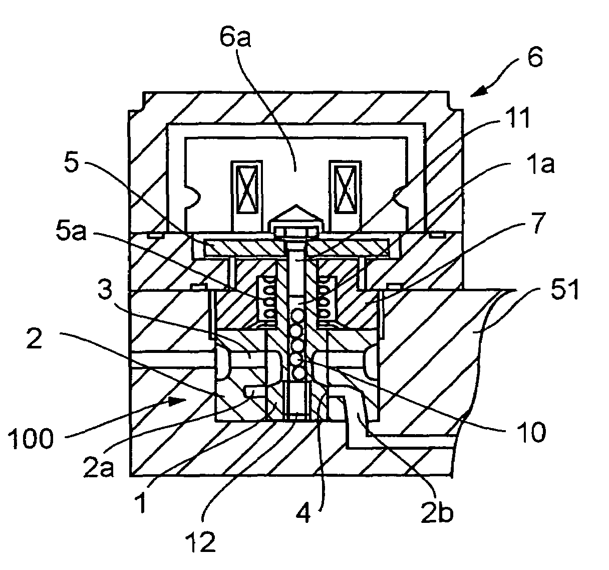
[0052]FIG. 1 is a sectional view of a substantial part of the first embodiment of the electromagnetic open / close valve with a poppet valve of an electromagnetic controlled unit injector for a diesel engine according to the present invention.

[0053]Referring to FIG. 1, reference numeral 6 is a solenoid device, 6a is a electromagnetic coil of the solenoid device, 1 is a poppet valve, 5a is a poppet valve spring, 2 is a valve seat member in which the poppet valve 1 is fitted reciprocatably, and 4 indicates the seat portion where the poppet valve 1 seats. The poppet valve 1 is reciprocated by the attraction of solenoid device 6 and the spring force of the poppet valve spring 5a. Reference numeral 2a is a fuel pool communicating to a fuel passage 2b, and 3 is a spill passage in the valve seat member 2.

[0054]Reference numeral 5 is an armature fixed to the upper end of the poppet valve 1. The armature can be attracted by the electromagnetic coil 6a.

[0055]Reference numeral 1a is an inside s...

second embodiment

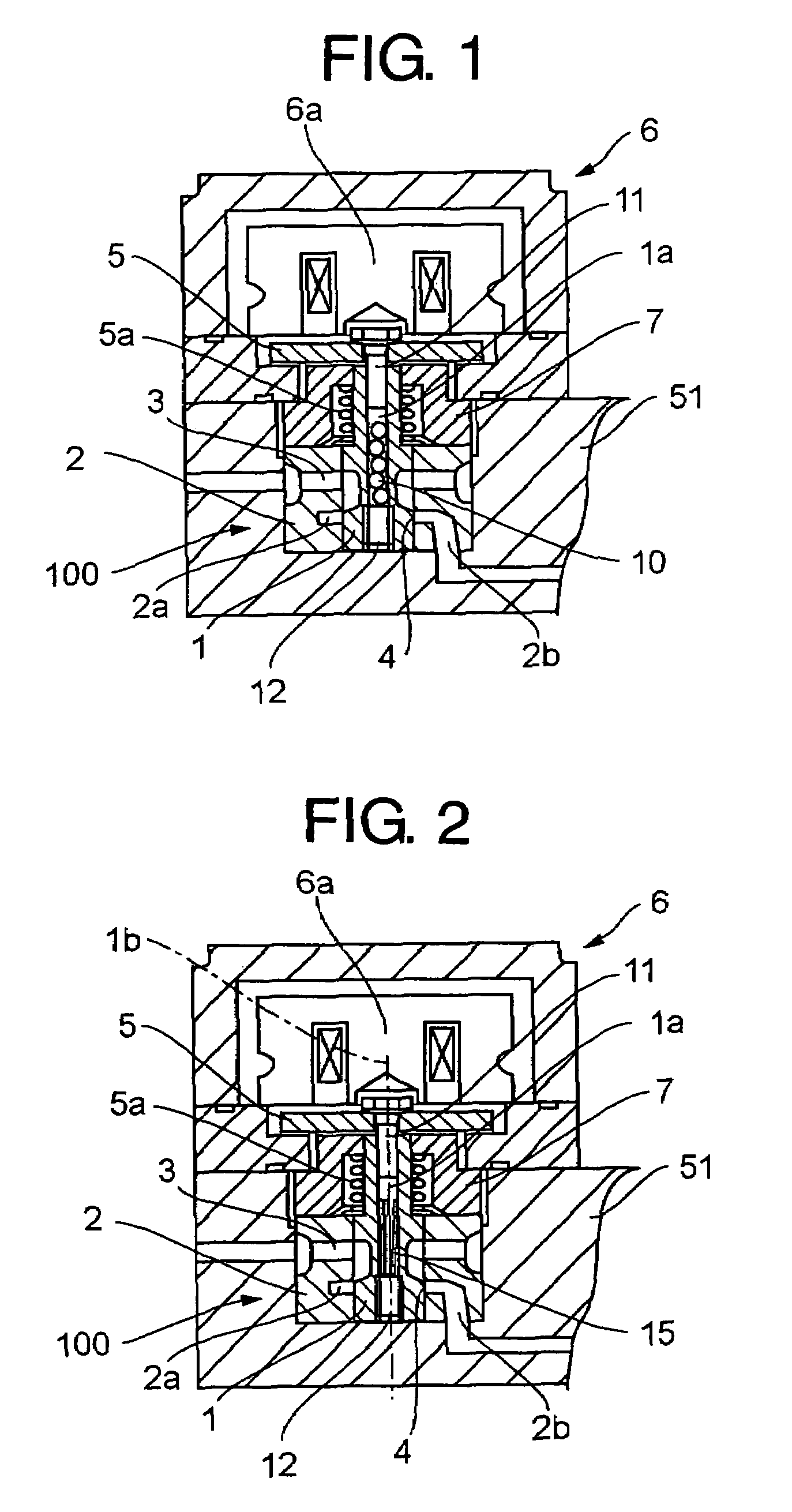
[0068]FIG. 2 is a drawing of the second embodiment corresponding to FIG. 1.

[0069]In the second embodiment, a plurality of needle bodies 15 are received in the inside space 1a of the poppet valve 1 instead of the spherical bodies 10. Each of the needle bodies 15 is of needle-like or bar-like shape made of steel, rubber, or plastic material. A plurality of them are received in the inside space 1a to be movable in the axial direction 1b of the poppet valve 1 and capable of contacting with each other on their outer surfaces.

[0070]The other construction is the same as that of the first embodiment of FIG. 1, and component members the same as those of FIG. 1 are designated with the same reference numerals.

[0071]According to the second embodiment, as the needle bodies 15 received in the inside space 1a of the poppet valve 1 are of needle-like or bar-like shape, the number of collisions of the needle-like bodies against the poppet valve in the axial direction can be increased compared to the...

third embodiment

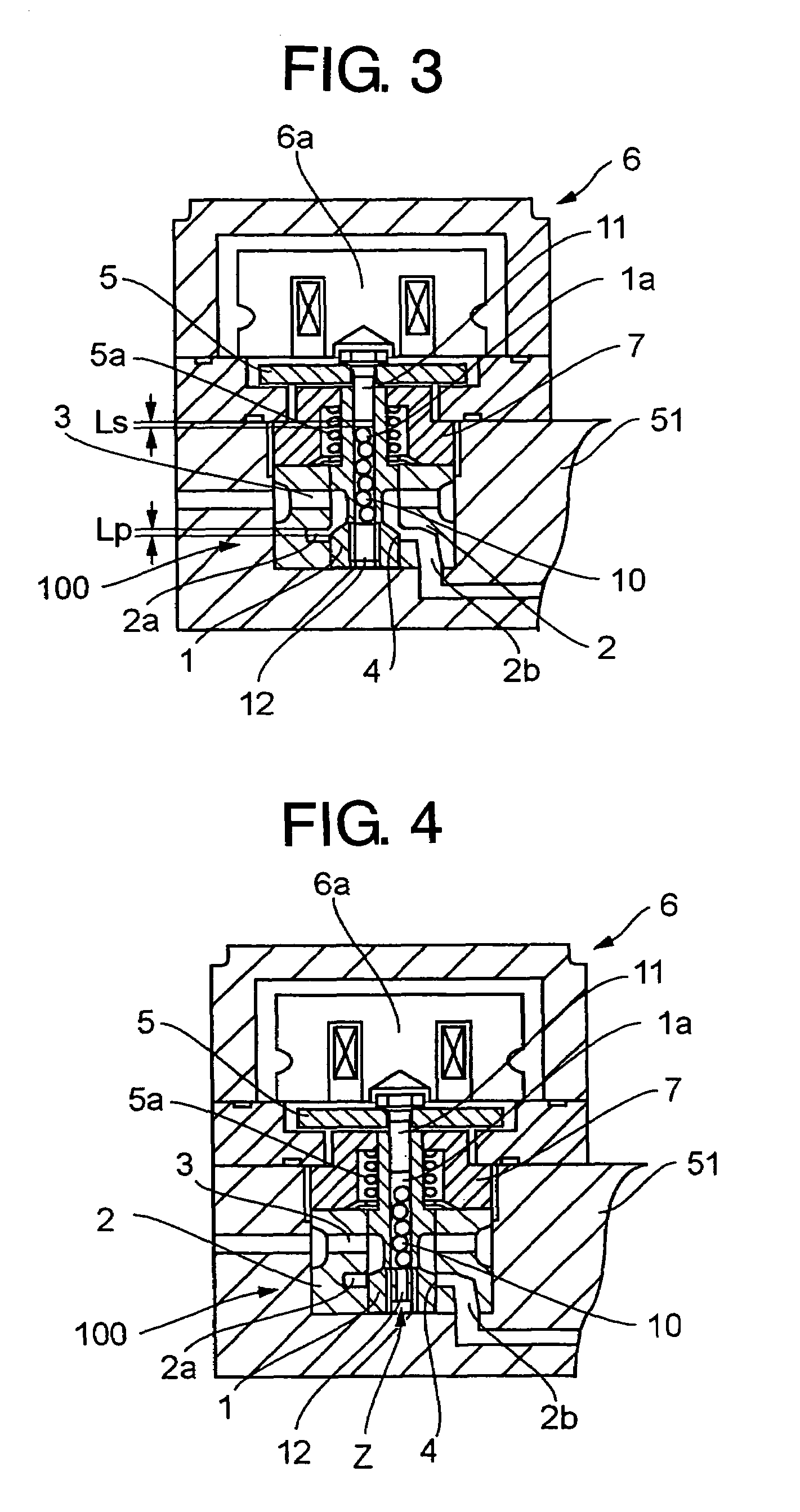
[0072]FIG. 4 is a drawing of the third embodiment corresponding to FIG. 1. FIG. 5 is a drawing for explaining the relation between the stroke of the poppet valve and the movable range of spherical bodies received inside the poppet valve in the third embodiment shown in FIG. 4. FIG. 6 is an enlarged detail of the part indicated with an arrow Z in the third embodiment shown in FIG. 4 and FIG. 5.

[0073]According to the third embodiment, a plurality of spherical bodies 10 are received in an inside space 1a of a poppet valve 1 so that they can move axially therein, contacting with each other when the poppet valve 1 reciprocates, the same as is in the first embodiment. A small hole 13 is provided in a plug 12 plugging the inside space 1a through which the inside space 1a is communicated to an outside fuel passage, i.e. a passage near the poppet valve 1.

[0074]The other construction is the same as that of the first embodiment of FIG. 1, and component members the same as those of FIG. 1 are d...


PUM


Abstract

An electromagnetic controlled fuel injection apparatus has a poppet valve which controls the beginning and end of fuel injection by reciprocation. Inertia force and friction force arising from the reciprocating motion of the poppet valve are utilized effectively to suppress bounce of the poppet valve. The poppet valve has a sealed inside space, and a plurality of mass objects are received in the inside space so that the mass objects can move axially while contacting with each other in the inside space due to the inertia force generated by the reciprocating motion of the poppet valve.

Description

BACKGROUND OF THE INVENTION[0001]1. Field of the Invention[0002]The present invention relates to an electromagnetic controlled fuel injection apparatus applied to an electromagnetic controlled unit injector, etc. for a diesel engine. Fuel injection timing thereof is controlled by means of a poppet valve which is reciprocated by means of a solenoid device to open or close a passage between a fuel passage to a plunger chamber where fuel is received and compressed to high pressure and a spill passage to a fuel return line.[0003]2. Description of the Related Art[0004]An electromagnetic controlled unit injector applied to a diesel engine is composed such that fuel injection timing is controlled through shutting-off or allowing communication of a fuel passage, which connects to a plunger room where fuel is introduced and compressed to high pressure, with a spill passage connecting to a fuel return line by closing and opening a poppet valve reciprocated by a solenoid device and a poppet va...

Claims


Application Information

Patent Timeline
Patent Type & Authority Patents(United States)
IPC IPC(8): F16K21/10F16K31/00
CPCF02M59/368F02M63/004F02M2200/304F02M2200/306Y10T137/785
Inventor KANEKO, TAKASHI
Owner MITSUBISHI HEAVY IND ENGINE & TURBOCHARGER LTD
Why Eureka
Try Eureka