Illumination assembly for a cannula/hub assembly
a technology which is applied in the field of cannula and hub assembly, can solve the problems of inability to illuminate the position on the body (e.g. of a person), the illumination feature described in the known assembly is less than optimal in procedures, and the lighting condition at the point of cannula insertion is compromised, so as to achieve the effect of improving monitoring
- Summary
- Abstract
- Description
- Claims
- Application Information
AI Technical Summary
Benefits of technology
Problems solved by technology
Method used
Image
Examples
first embodiment
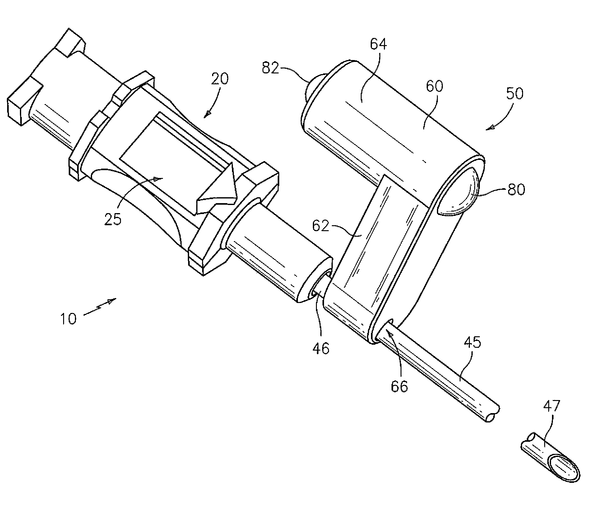
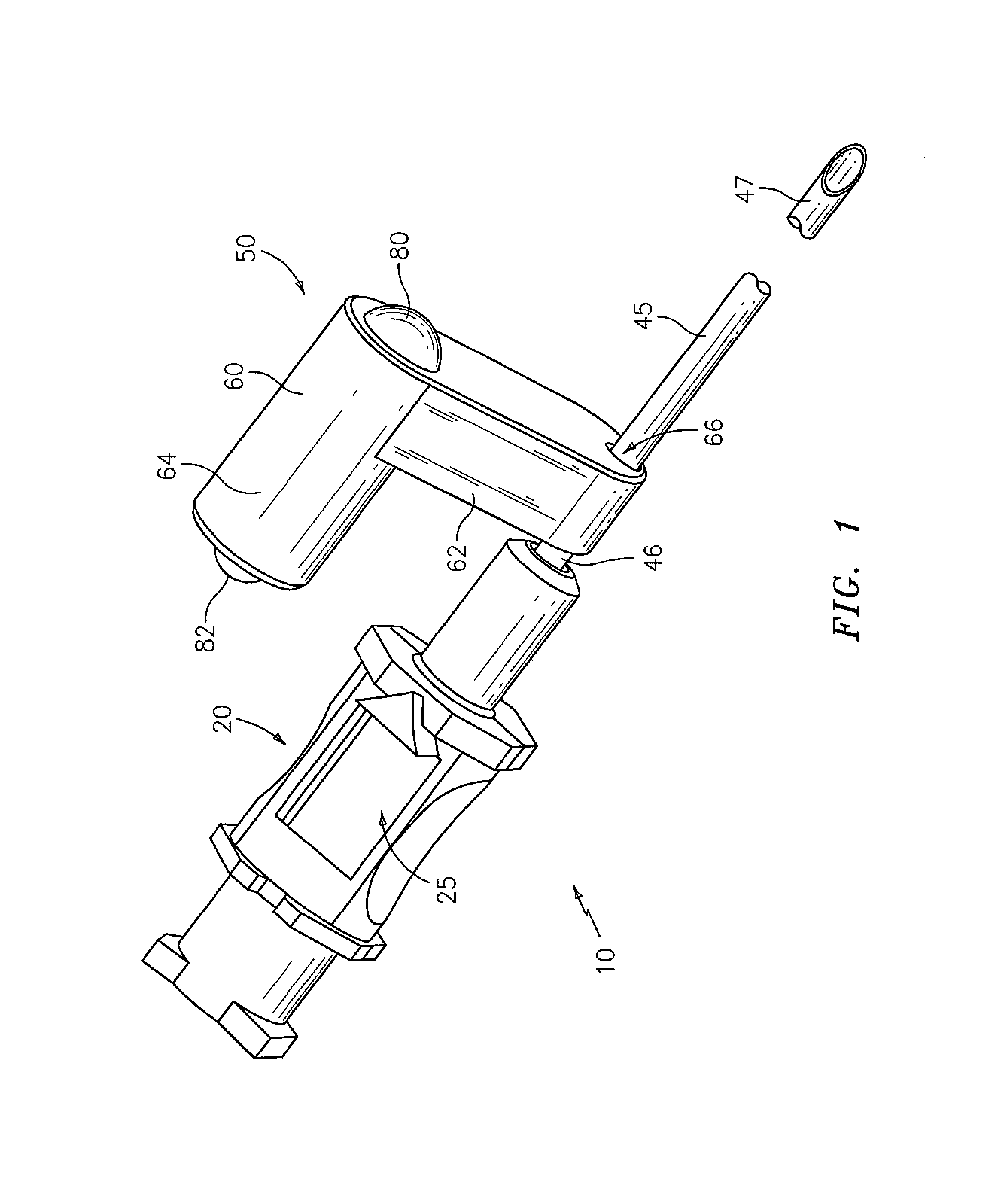
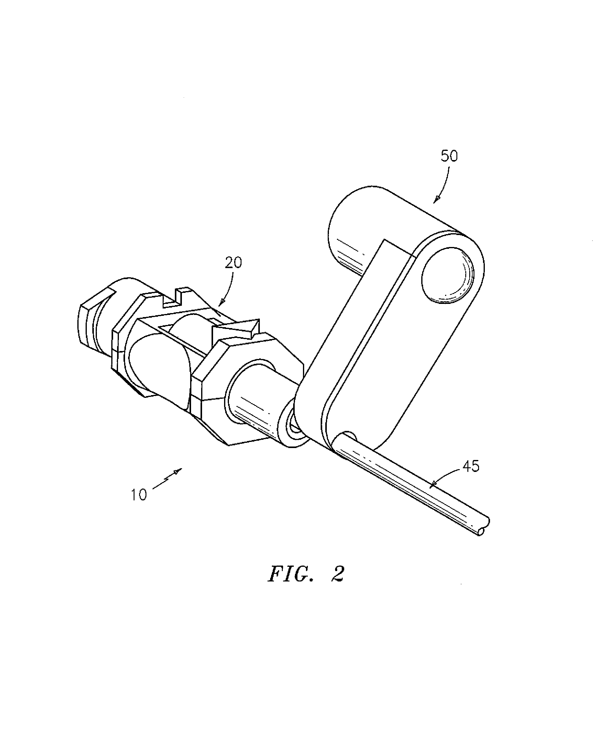
[0023]Thus, reference is first made to FIGS. 1 and 2 a more detailed description of the present invention. In particular, FIGS. 1 and 2 illustrate an assembly, generally indicated at 10, comprising a cannula / hub assembly generally indicated at 20 and an illumination assembly generally indicated at 50.
[0024]By way of background and for the convenience of the reader, cannula / hub assembly 20 may be utilized in a flashback arrangement, wherein the cannula / hub assembly 20 comprises a hub, generally indicated at 25 and a cannula 45 coupled to hub 25 to permit communication of a bodily fluid (e.g. CSF or blood) with hub 25. Again, by way of example and not limitation, hub 25 may be a magnifying hub as set forth in greater detail in the aforementioned U.S. Pat. No. 6,656,161. For purposes of the present invention, cannula 45 preferably has a first end 46 securable to or within hub 25 and a second end 47 dimensioned to permit withdrawal of the bodily fluid from or inject fluid into a body. C...
second embodiment
[0030]Reference is now made to FIGS. 3 and 4 for a discussion of the present invention in accordance with a Here, an assembly, generally indicated at 100, comprises cannula / hub assembly 20 and an illumination assembly, generally indicated at 150, preferably comprising a housing 160 and light-emitting element 80 mounted in and / or on housing 160 in a similar manner to which light-emitting element 80 is mounted to or in housing 60. That is, in the embodiment of FIGS. 3 and 4, again light emitting element 80 preferably has one end thereof extending outwardly from housing 160, and again is preferably battery powered and manually operated by way of a push button, such as that positioned on the opposing surface of housing 80 and identical to push button 82.
[0031]In this second embodiment, housing 160 comprises an arm 162 that couples (preferably in a removable fashion (such as sliding on in a friction fit), but not necessarily) to a luer lock 30 of assembly 20. Depending on size and weigh...
PUM
 Abstract
Description
Claims
Application Information
 - R&D
- Intellectual Property
- Life Sciences
- Materials
- Tech Scout
- Unparalleled Data Quality
- Higher Quality Content
- 60% Fewer Hallucinations
Browse by: Latest US Patents, China's latest patents, Technical Efficacy Thesaurus, Application Domain, Technology Topic, Popular Technical Reports.
© 2025 PatSnap. All rights reserved.Legal|Privacy policy|Modern Slavery Act Transparency Statement|Sitemap|About US| Contact US: help@patsnap.com


