
Enhanced ion desolvation for an ion mobility spectrometry device

a technology of mobility spectrometry and enhanced ion desolvation, which is applied in the field of enhanced ion desolvation for ion mobility spectrometry, can solve the problems of peak broadening, loss of separation resolution, and significant compromise of the performance of the faims cell, and achieve the effect of promoting evaporation

Active Publication Date: 2008-04-01
THERMO FINNIGAN
View PDF26 Cites 10 Cited by
  • Summary
  • Abstract
  • Description
  • Claims
  • Application Information

AI Technical Summary

Benefits of technology

[0005]According to one embodiment of the invention, a mass spectrometer apparatus is provided that includes an ion source for generating analyte ions, an ion mobility spectrometry device having a plurality of electrodes and being operable to separate the analyte ions according to their mobilities, and at least one capillary for transporting the analyte ions from the ion source to the ion mobility spectrometry device. The capillary is heated to promote evaporation of any residual liquid solvent that enters the capillary inlet. The use of a heated capillary for droplet desolvation avoids the need to provide a counterflow gas and the associated disadvantages.

Problems solved by technology

The performance of a FAIMS cell may be significantly compromised if liquid-phase material is admitted into the separation region.
If the droplet desolvation process does not proceed to completion (which may tend to occur at high liquid flow rates), partially desolvated droplets may enter the FAIMS cell, causing several problems.
First, the presence of the droplets may interfere with the separation of the ions, resulting in a loss of separation resolution (i.e., peak broadening).
Second, the droplets may come into contact with the electrode surfaces, causing signal carry-over.
Finally, accumulation of liquid on the electrodes will eventually cause the high-voltage asymmetric waveform to discharge, rendering the FAIMS cell inoperable.
However, use of the counterflow gas approach carries several disadvantages.
First, introduction of the counterflow gas significantly increases overall pumping requirements.
Additionally, the flow rate of the counterflow gas must be carefully controlled, since inadequate or excessive flow rates can change the rate of ion transport through the FAIMS cell, in turn affecting the transmission of selected ion species.

Method used


Image

  • Enhanced ion desolvation for an ion mobility spectrometry device
  • Enhanced ion desolvation for an ion mobility spectrometry device
  • Enhanced ion desolvation for an ion mobility spectrometry device

Examples


Embodiment Construction

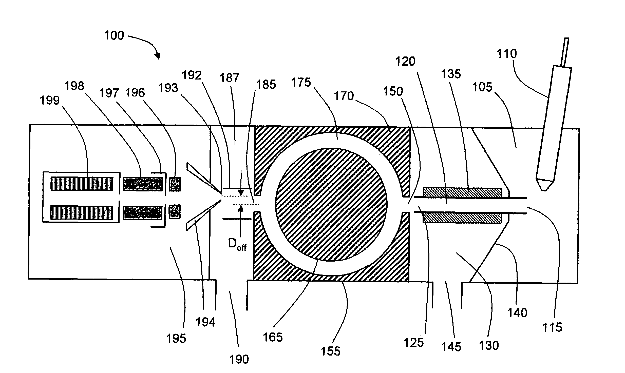
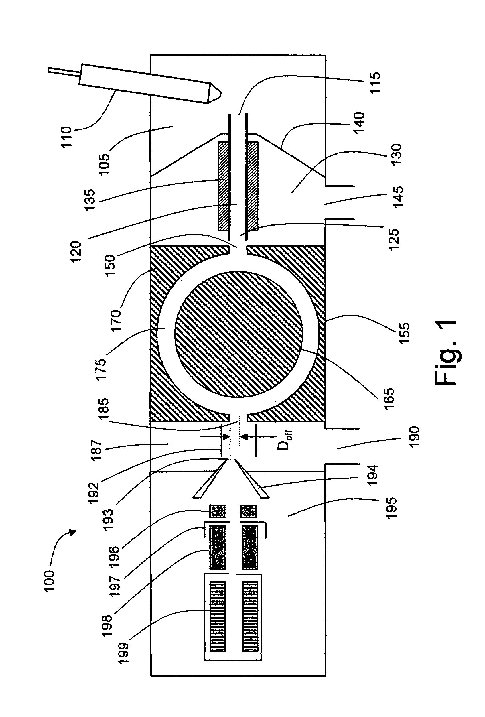
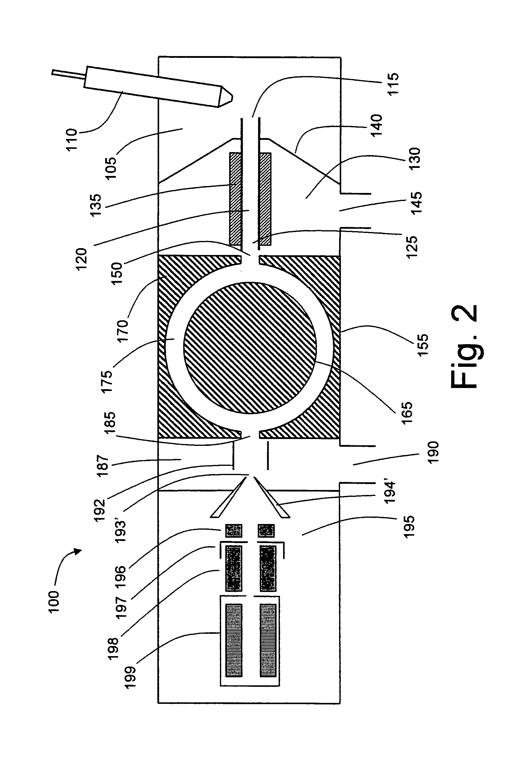
[0014]FIG. 1 symbolically depicts a mass spectrometer system 100 configured in accordance with a first embodiment of the invention. A solution of sample to be analyzed is introduced as a spray of liquid droplets into an ionization chamber 105 via probe 110. Ionization chamber 105 is maintained at a high pressure relative to the regions downstream in the ion path, typically at or near atmospheric pressure. Probe 110 may be configured as an electrospray ionization (ESI) probe, wherein a high DC voltage (either positive or negative) is applied to the capillary through which the sample solution flows. This voltage imparts a charge to the droplets as they are emitted from the capillary exit. The charge accumulates at the droplet surface during solvent evaporation, causing droplet fragmentation and the formation of analyte ions. Other suitable ionization techniques may be utilized in place of ESI, including without limitation such well-known techniques as atmospheric pressure chemical ion...


PUM


Abstract

An ion spectrometer apparatus is disclosed having an ion source, an ion mobility spectrometer device such as a FAIMS cell, and a capillary for transporting ions from the ion source to the entrance of the FAIMS cell. The capillary is heated to promote evaporation of solvent from incompletely desolvated droplets entering the capillary inlet, thereby preventing or minimizing operational problems associated with the presence of wet material in the FAIMS cell. The FAIMS cell may be used to selectively transmit ions to a mass analyzer.

Description

FIELD OF THE INVENTION[0001]The present invention relates generally to ion mobility spectrometry, and more particularly to the desolvation of ions prior to introduction into a ion mobility spectrometry device, such as a high field asymmetric ion mobility spectrometry (FAIMS) cell.BACKGROUND OF THE INVENTION[0002]In ion mobility spectrometry devices, separation of gas-phase ions is accomplished by exploiting variations in ion drift velocities under an applied electric field arising from differences in ion mobilities. One well-known type of ion mobility spectrometry device is the FAIMS cell, which separates ions on the basis of a difference in the mobility of an ion at high field strength (commonly denoted as Kh) relative to the mobility of the ion at low field strength (commonly denoted as K). Briefly described, a FAIMS cell consists of a pair of spaced apart electrodes that define therebetween a separation region through which a stream of ions is directed. An asymmetric waveform com...

Claims


Application Information

Patent Timeline
Patent Type & Authority Patents(United States)
IPC IPC(8): H01J49/04
CPCG01N27/624H01J49/0404H01J49/049
Inventor BELFORD, MICHAEL W.
Owner THERMO FINNIGAN
Learn More