Slide fastener chain

a fastener and slide technology, applied in the direction of slide fasteners, press-button fasteners, snap fasteners, etc., can solve the problems of unfavorable tactile feeling received from the fastener element b>102/b>, and achieve the effect of excellent tactile feel and easy adoption

Inactive Publication Date: 2008-04-08
YKK CORP
View PDF10 Cites 34 Cited by
  • Summary
  • Abstract
  • Description
  • Claims
  • Application Information

AI Technical Summary

Benefits of technology

[0014]As a consequence, the surface of the fastener element of injection type in the fastener chain has a curved face swelling out smoothly and circularly. Thus, the injection type fastener element provides an excellent tactile feeling, thereby obtaining a fastener chain securing an excellent tactile feeling and a beautiful appearance.
[0016]Consequently, the supporting portion whose rear surface portion is wider than the front surface portion can be provided at the middle portion of the injection type fastener element, whereby a fastener chain having a beautiful appearance in design terms can be finished easily.
[0018]As a consequence, the front surface portion and the rear surface portion of the injection type fastener element are finished into the same contour so that the surface of the fastener element having a high engagement strength can be finished into a beautiful appearance and to have an excellent tactile feel.
[0022]As a consequence, the curved face provided on the surface of the injection type fastener element is achieved depending on different mounting conditions. Thus, there is an advantage that the curved face can be selected depending on an intended purpose, whereby the fastener chain can be used depending on an intended purpose.
[0024]As a consequence, the curvature to be provided on the front surface of the injection type fastener element can be achieved easily by using specific values, and they can be adopted easily depending on an intended purpose, thereby providing a fastener chain having fastener elements securing an excellent tactile feel. Therefore, as described above, the effects which the present invention can exert are very remarkable.

Problems solved by technology

Therefore, both the front surface and rear surface are formed into a flat plane, thereby providing such a problem that the tactile feeling received from the fastener element 102 is not favorable.

Method used


Image

  • Slide fastener chain
  • Slide fastener chain
  • Slide fastener chain

Examples


first embodiment

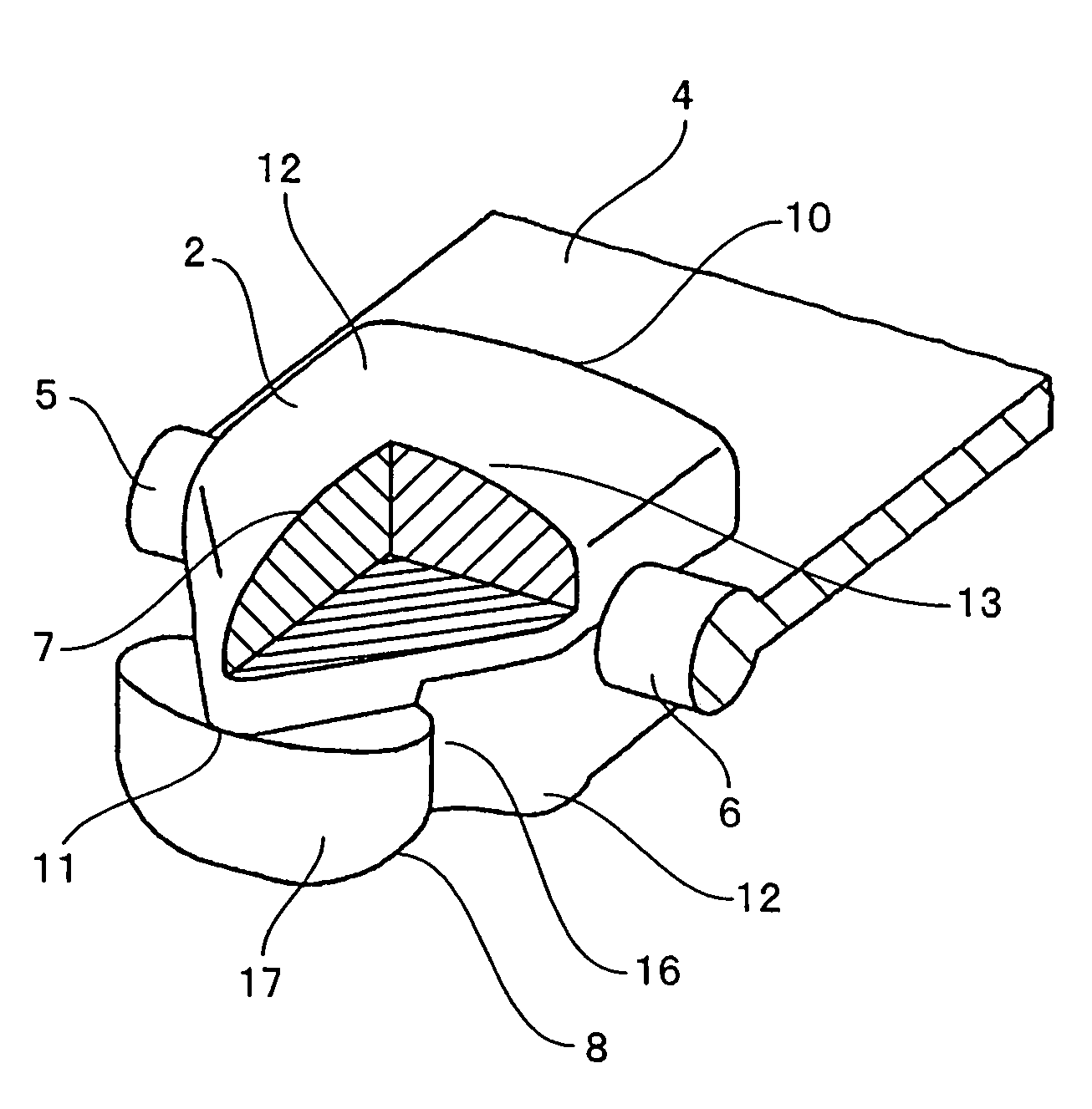
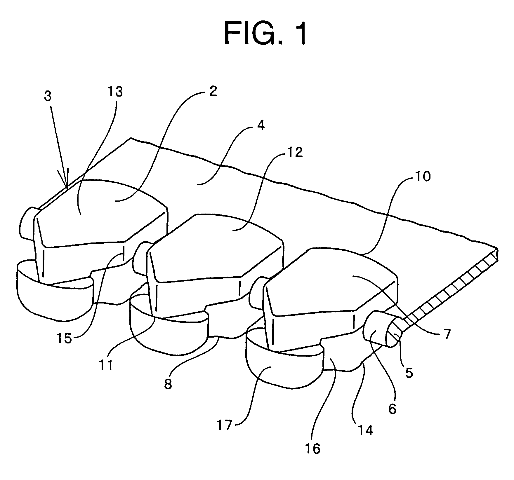
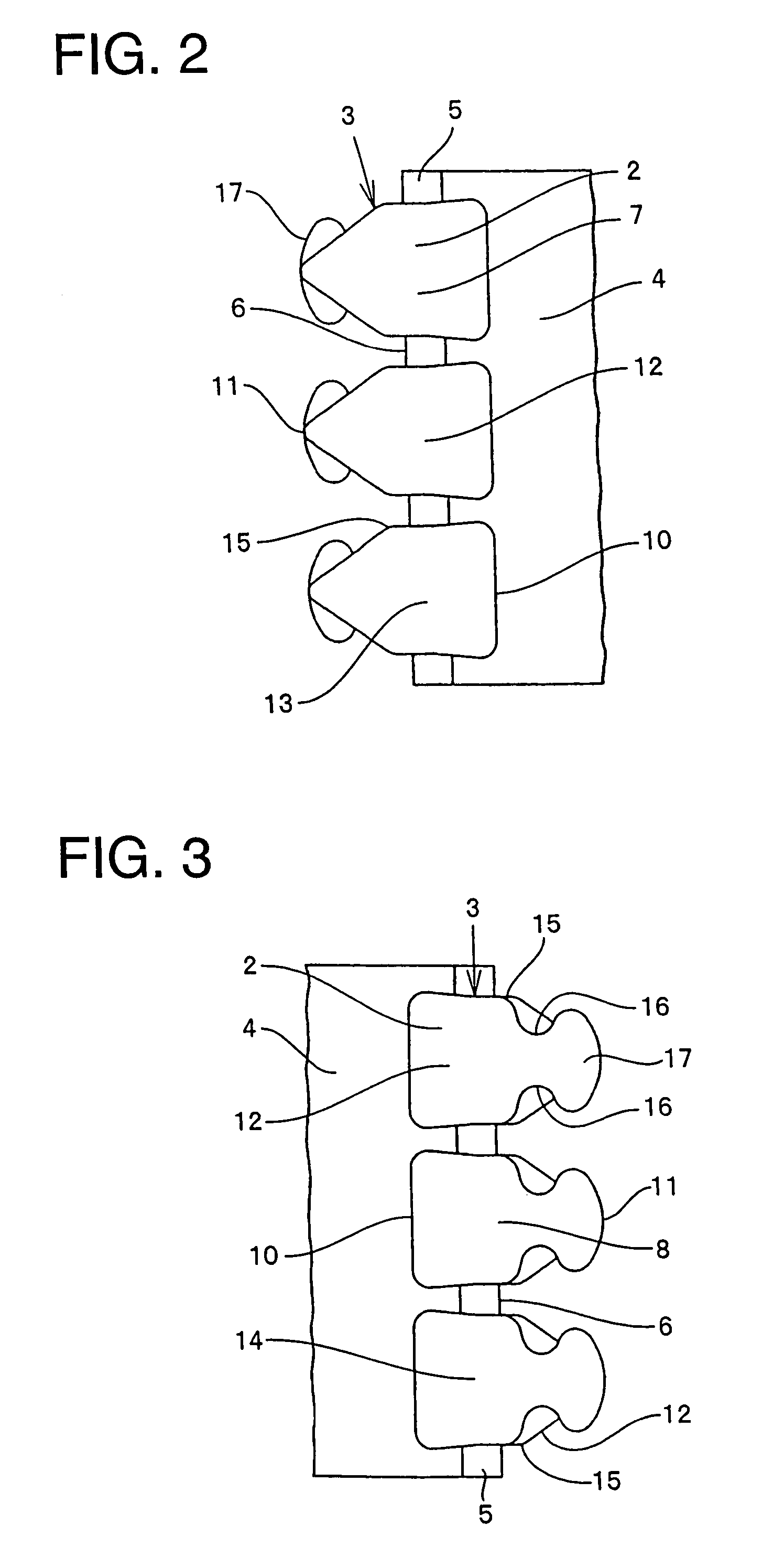
[0041]A slide fastener chain of the present invention will be described. In a fastener chain 1 according to a first embodiment shown in FIGS. 1 to 7, fastener elements 2 of injection type as a single unit are molded by injection molding means using thermoplastic resin such as polyamide, polyacetal, polypropylene, or polybutylene terephthalate on an expanded core thread 5 provided on opposing side edges 6 of a pair of right and left fastener tapes 4. The fastener elements 2 are arranged by plural quantities at a predetermined interval in the length direction of the fastener chain 1 to form a fastener element row 3. The length direction of the fastener chain 1 is the width direction of the fastener element 2, and a direction perpendicular to the length direction of the fastener chain 1 is the length direction of the fastener element 2.

[0042]The fastener element 2 comprises a front surface portion 7 and a rear surface portion 8 disposed on both the front and rear surfaces of the fasten...

second embodiment

[0046]In a slide fastener chain according to a second embodiment shown in FIG. 8, fastener elements 2 are molded on opposing side edges 6 of fastener tapes 4 by injection molding means using the same thermoplastic resin as the first embodiment. In the fastener element 2, a front surface portion 7 is formed on the front side of the fastener tape 4, and a rear surface portion 8 is formed on the rear side thereof. In the front surface portion 7, a supporting portion 12 is formed from a proximal portion 10 of the fastener element 2 up to a front end 11 thereof, and this supporting portion 12 is formed into a shape whose width dimension decreases gradually from a middle portion 15 of the fastener element 2 to the front end 11, that is, a substantially triangular shape. In addition, the surface of the fastener element 2 is formed into a curved shape projecting upward and convexly from the proximal portion 10 to the front end 11, that is, is formed into a curved face 13 which curves so tha...

third embodiment

[0047]In a slide fastener chain according to a third embodiment shown in FIGS. 9 and 10, fastener elements 2 are molded on opposing side edges 6 of fastener tapes 4 by injection molding means using the same thermoplastic resin as the above-described embodiments. In each fastener element 2, a front surface portion 7 is formed on the front side of the fastener tape 4, and a rear surface portion 8 is formed on the rear side thereof. In the front surface portion 7, a supporting portion 12 is formed from a proximal portion 10 of the fastener element 2 up to a front end 11 thereof, and this supporting portion 12 is formed into a shape whose width dimension decreases gradually from a middle portion 15 of the fastener element 2 to the front end 11 thereof, that is, a substantially triangular shape. In addition, the surface of the fastener element 2 is formed into a shape in which the central line from the proximal portion 10 up to the front end 11 is curved convexly, that is, projected conv...


PUM


Abstract

A fastener chain, in which fastener elements each formed into a single unit of synthetic resin are attached at a constant interval along opposing side edges of a pair of fastener tapes, a front surface portion and a rear surface portion are provided on the front and rear sides of the fastener element, the surface of the front surface portion is formed into a curved face entirely swelling out circularly and upward while the rear surface portion is formed into a flat plane which is entirely even, and the front surface and the rear surface of the fastener element may have different shapes or the same shape so as to secure a fastener chain having an excellent tactile feel and beautiful appearance.

Description

BACKGROUND OF THE INVENITON[0001]1. Field of the Invention[0002]The present invention relates to a slide fastener chain in which fastener elements of injection type are attached to opposing side edges of a pair of fastener tapes by injection molding means using synthetic resin.[0003]2. Description of the Related Art[0004]In a fastener element of injection type according to Japanese Utility Model Publication No. 63-7049, as shown in FIG. 12, fastener elements 102 of injection type are attached to opposing side edges 106 of a pair of fastener tapes 104 by injection molding means using synthetic resin such that the front surface and rear surface of each of the fastener elements 102 have different shapes. In the front surface, a leg portion 130 is provided projectingly from a proximal end 140 of the fastener element 102 to a front end thereof, a neck portion 116 is provided in the middle of the leg portion 130, and an expanded coupling head 117 is provided at a front end of the neck por...

Claims


Application Information

Patent Timeline
Patent Type & Authority Patents(United States)
IPC IPC(8): A44B19/04
CPCA44B19/06Y10T24/2543Y10T24/2539Y10T24/2557
Inventor HIMI, NAOYUKI
Owner YKK CORP
Why Eureka
Try Eureka