
Cargo container with insulated floor

a cargo container and floor technology, applied in the direction of transportation and packaging, packaging, window arrangements, etc., can solve the problems of significant heat loss through the floor or other places, and reducing the thermal efficiency of the cargo container

Active Publication Date: 2008-04-08
MARTIN MARIETTA MATERIALS
View PDF164 Cites 27 Cited by
  • Summary
  • Abstract
  • Description
  • Claims
  • Application Information

AI Technical Summary

Benefits of technology

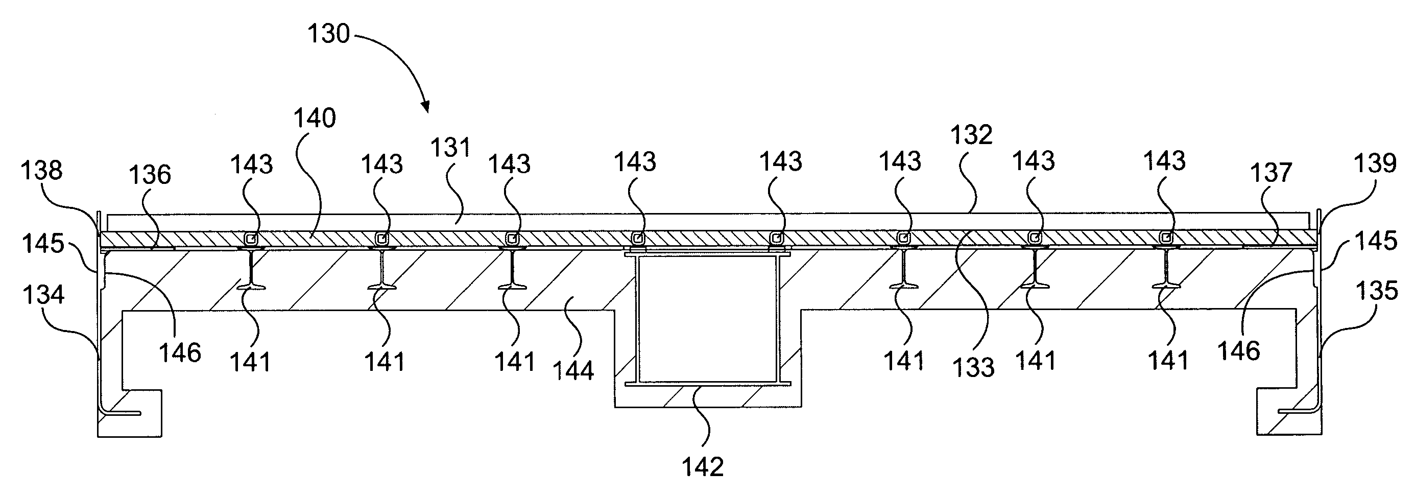
"The present invention provides an insulated floor for a cargo container that includes a floor panel, insulating members, and structural members. The insulating members are attached to the floor panel and the bottom surface of the floor panel, while the structural members are attached to the insulating members. An insulation layer is also included that covers the bottom surface of the floor panel and the structural members. The floor panel has a longitudinal axis, and the insulating members are attached to the floor panel at the first and second ends. The floor panel also includes a center sill, I-Beams, and a second insulation layer that covers the center sill, I-Beams, and the interior surfaces of the first and second side sills. The technical effects of the invention include improved insulation, reduced weight, and increased durability of the cargo container floor."

Problems solved by technology

In these containers, a significant amount of heat loss occurs through the floor or other places with thermal shorts.
Since the underside of the floor is exposed to ambient conditions, the conductive properties of the metal floor cause heat loss through the floor and decrease the thermal efficiency of the cargo container.
These structural members also contribute to the heat loss through the floor and further decrease the thermal efficiency of the cargo container.

Method used


Image

  • Cargo container with insulated floor
  • Cargo container with insulated floor
  • Cargo container with insulated floor

Examples


Embodiment Construction

[0019]A. Introduction

[0020]Apparatus consistent with the present invention will now be described with respect to an embodiment of an insulated cargo container, or a boxcar. The invention as claimed, however, is broader than boxcars and extends to other large insulated cargo containers, such as, shipping containers used on seagoing container vessels, truck trailers, straight trucks, refrigerated buildings, or the like.

[0021]B. Apparatus

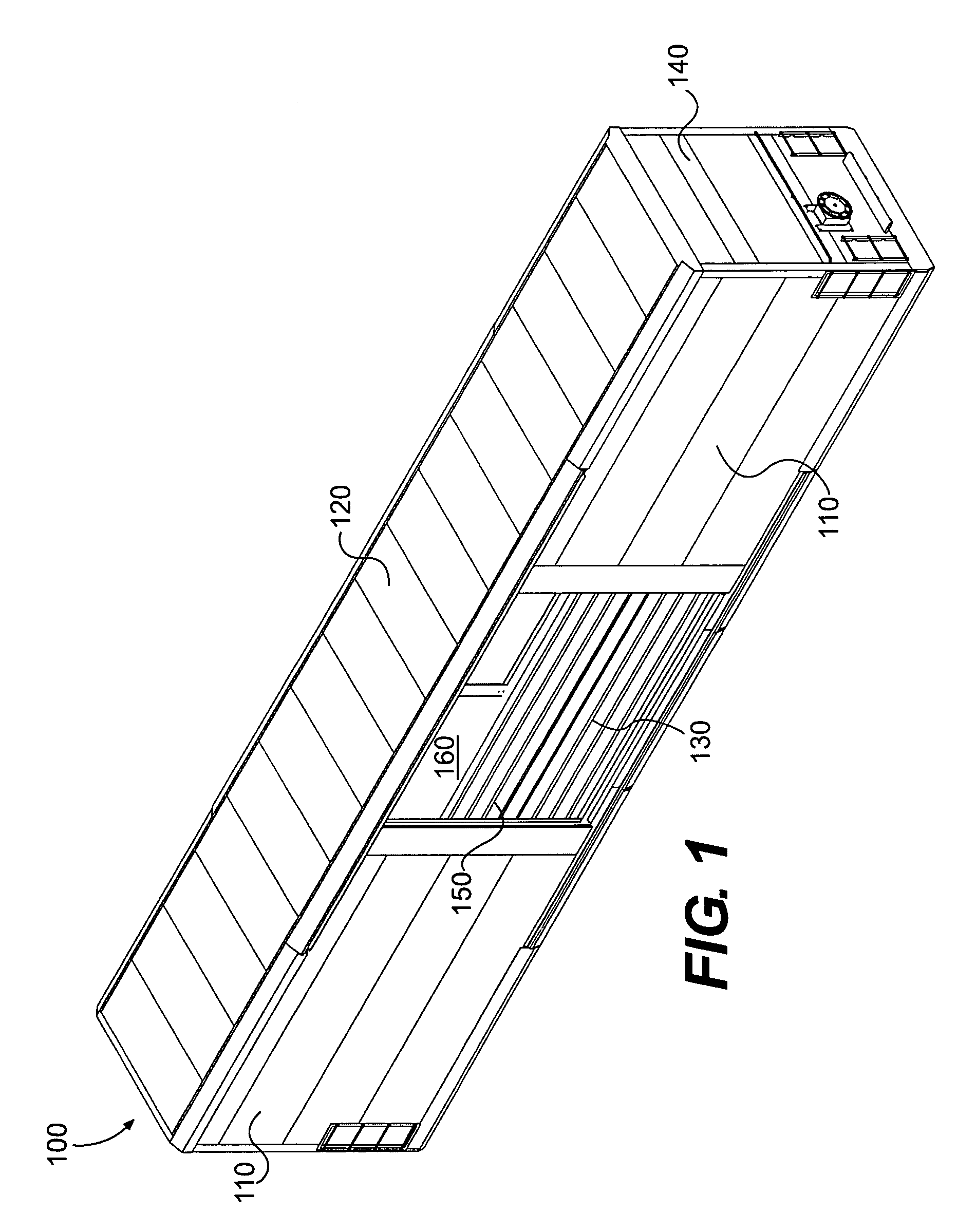
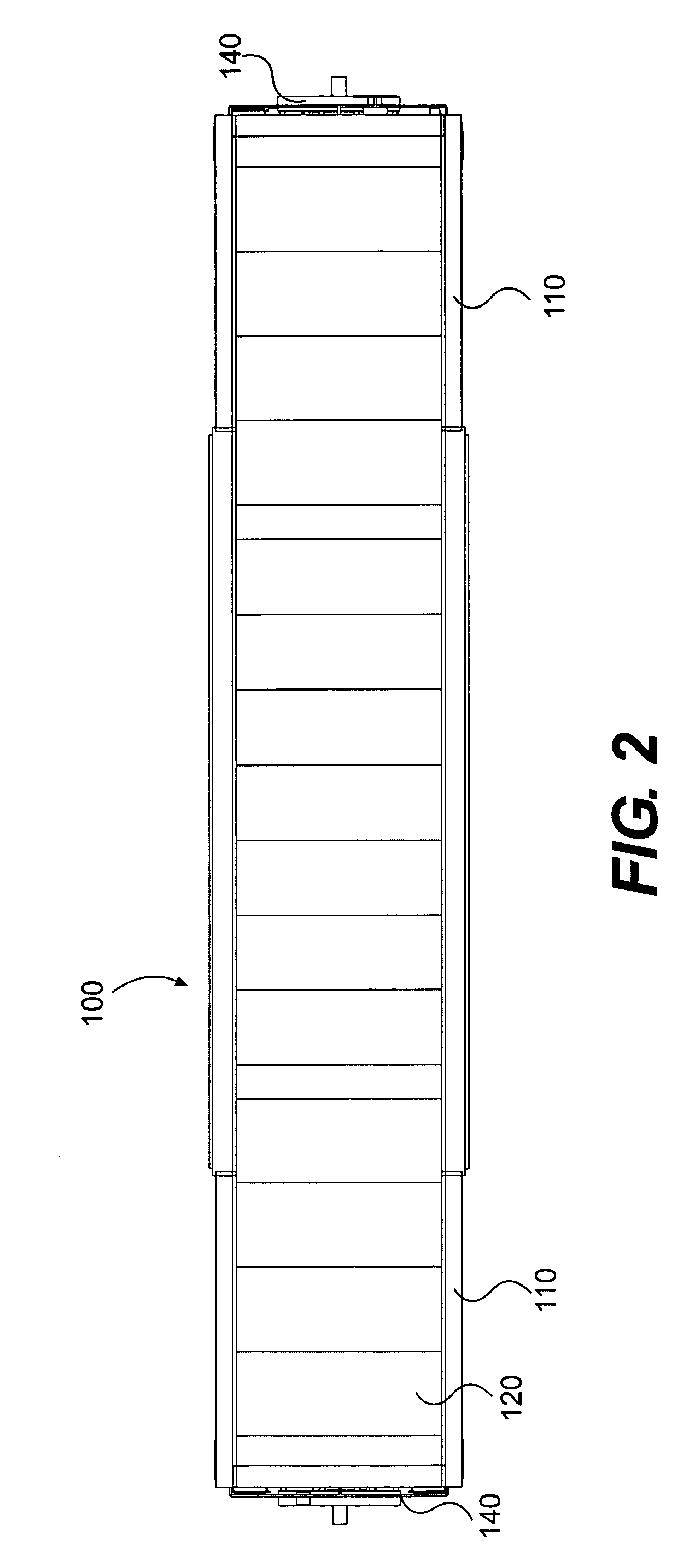
[0022]FIGS. 1-3 illustrate three views of an insulated boxcar consistent with one embodiment of the invention. As shown in FIGS. 1-3, an insulated boxcar 100 includes wall panels 110, a roof 120, a floor 130, end walls 140, and a door opening 150. Wall panels 110, roof 120, floor 130, and end walls 140 combine to form an enclosure 160. Door opening 150 provides access to enclosure 160. Enclosure 160 can be used to store articles at specified temperatures. In one implementation, boxcar 100 will include a refrigeration mechanism to maintain a specified t...


PUM


Abstract

The present invention relates to an insulated cargo container with an insulated floor. The insulated floor includes insulating members and insulation layers in order to remove thermal shorts and increase the thermal efficiency of the cargo container.

Description

I. BACKGROUND[0001]A. Technical Field[0002]The present invention relates to a cargo container with an insulated floor. In one embodiment, the cargo container is a railroad boxcar.[0003]B. Related Art[0004]Currently, many shippers utilize refrigerated and / or insulated large cargo containers (such as boxcars) to transport items that require the maintenance of specified temperatures during transit. Because these containers are required to maintain certain temperatures, the thermal efficiency of these containers is an important feature. Thermal efficiency is characterized by the thermal conductivity of a particular component or its inverse, its resistance to heat transfer, commonly referred to as an R-value.[0005]In these containers, a significant amount of heat loss occurs through the floor or other places with thermal shorts. A typical container floor is constructed of metal, which is highly conductive to heat transfer. Since the underside of the floor is exposed to ambient conditions...

Claims


Application Information

Patent Timeline
Patent Type & Authority Patents(United States)
IPC IPC(8): B65D88/00B61D17/00B61D3/00
CPCB61D17/18B65D90/06
Inventor SEITER, JOSEPH
Owner MARTIN MARIETTA MATERIALS
Learn More