Pressure intensifier

a technology of pressure intensifier and fluid, which is applied in the direction of fluid-pressure converter, piston pump, positive displacement liquid engine, etc., can solve the problem of relativly minimal modifications in order to decouple the two fluids, and achieve the effect of preventing cavitation phenomena

Active Publication Date: 2008-04-08
MINIBOOSTER HYDRAULICS
View PDF13 Cites 52 Cited by
  • Summary
  • Abstract
  • Description
  • Claims
  • Application Information

AI Technical Summary

Benefits of technology

[0013]Preferably, the control valve is connected to the return connector by a path which extends in an area between the high-pressure piston and the low-pressure piston through the low-pressure cylinder. In this way, the area between the high-pressure piston and the low-pressure piston is filled with fluid that is displaced from the low-pressure chamber delimited by the low-pressure cylinder and the low-pressure piston. Cavitation phenomena can be prevented. When the low-pressure piston is moved such that the high-pressure chamber is enlarged, then the chamber between the high-pressure piston and the low-pressure piston is also enlarged, i.e., the space within the low-pressure cylinder. This chamber can then be refilled via the control valve.
[0014]Preferably, the low-pressure piston has at the periphery of at least one end face a circumferentially extending recess, and a correlated connection between the control valve and the low-pressure cylinder opens into the circumferential wall of the low-pressure cylinder in the area of its end face. In this way, the low-pressure piston can be reciprocated up to the stop position within the low-pressure cylinder. However, a driving action by means of a fluid is still possible even when this fluid is not introduced at the end face into the low-pressure cylinder but via the peripheral wall. The fluid then reaches the recess and can flow farther from there.
[0015]Preferably, a throttled auxiliary control path is arranged between the supply connector and control connector of the control valve and enables switching of the control valve into the first switching position. The auxiliary control path enables reliable starting of the pressure intensifier even after an extended downtime. The control valve has in fact always a defined switching position when it is pressurized.
[0016]In this connection, it is particularly preferred that the auxiliary control path is arranged in a valve element of the control valve. It is then possible to ensure that the auxiliary control path is interrupted when the control valve is in the second switching position.

Problems solved by technology

In comparison to the known device, only relatively minimal modifications are possible in order to decouple the two fluids.

Method used


Image

  • Pressure intensifier
  • Pressure intensifier

Examples


Embodiment Construction

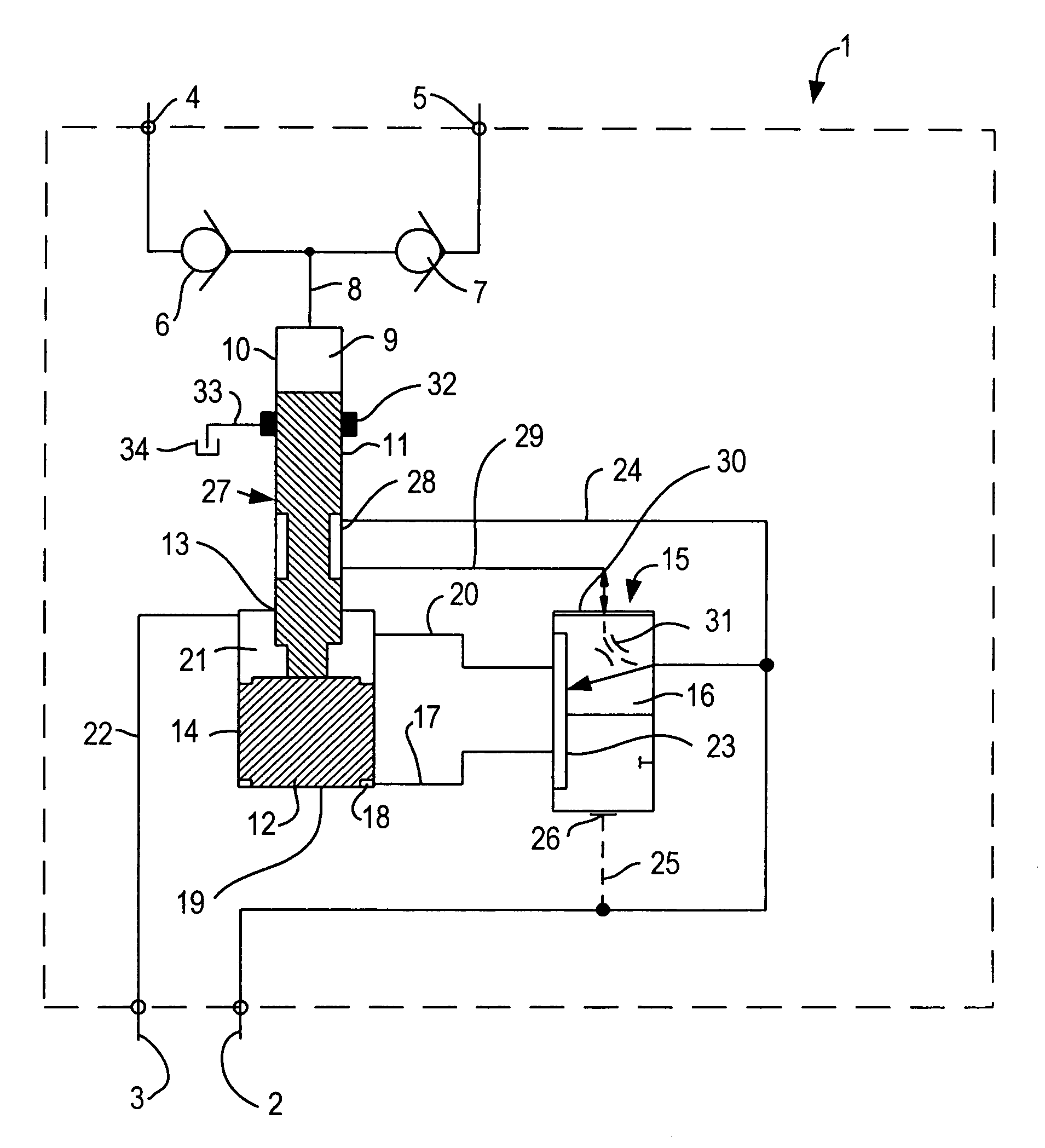
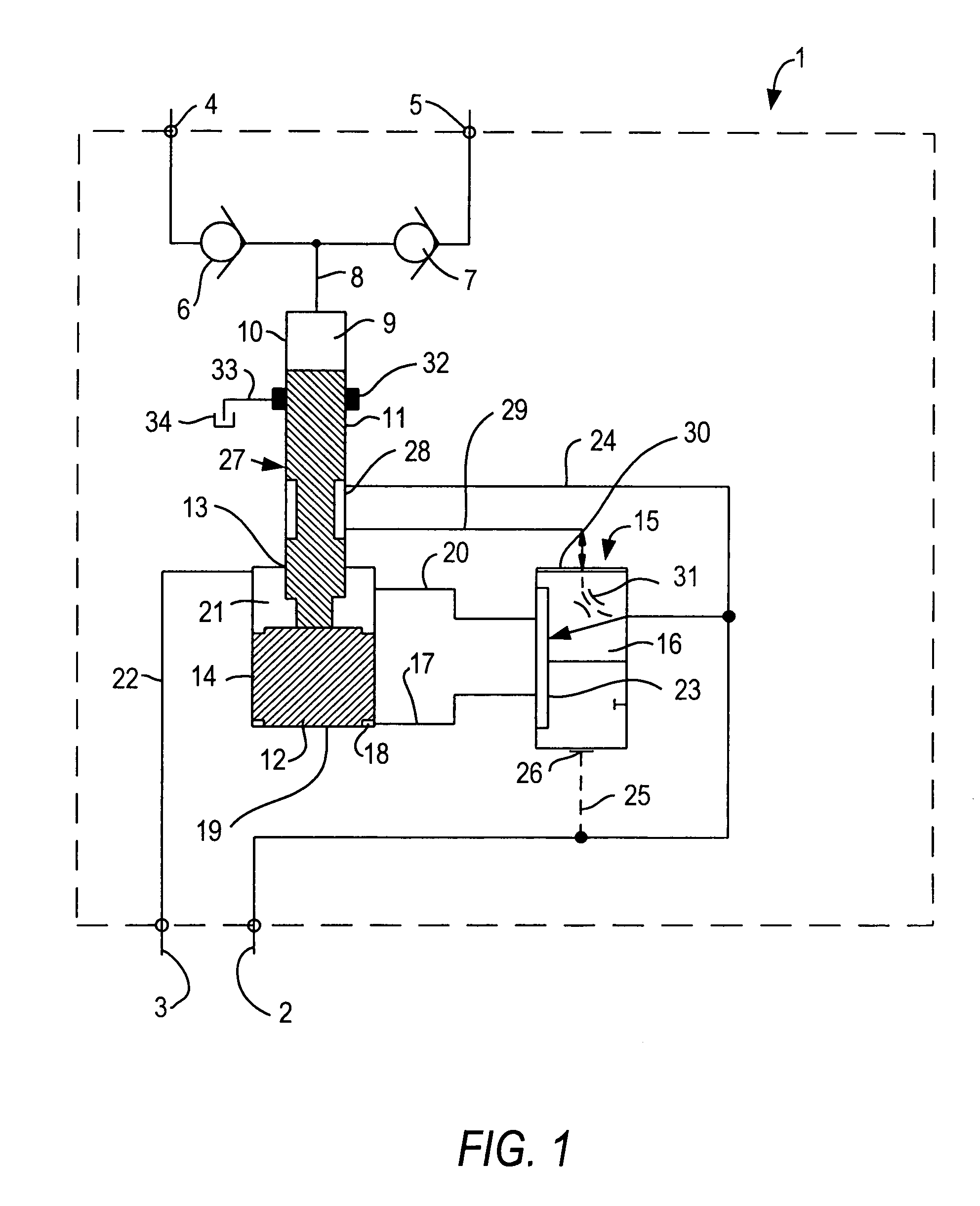
[0019]A pressure intensifier 1 has a supply connector 2 via which a driving fluid, for example, a first hydraulic liquid at a certain pressure, is supplied. This hydraulic liquid can be returned via a return connector 3. For example, the supply connector 2 can be connected to a pump, not illustrated in detail, and the return connector 3 to a tank, not illustrated in detail.

[0020]Moreover, the pressure intensifier 1 has a high-pressure outlet 4 and a high-pressure inlet 5, both connected to a high-pressure circuit in which a second hydraulic liquid circulates. The second hydraulic liquid, referred to in the following as the pumping liquid, is at a higher pressure than the first hydraulic liquid that is referred to as the driving liquid. It is desired to prevent that the driving liquid and the pumping liquid mix with one another. The pumping liquid is circulated via the high-pressure inlet 5 and the high-pressure outlet 4.

[0021]Between the high-pressure inlet 5 and the high-pressure o...


PUM


Abstract

A pressure intensifier for fluids has an intensifier piston with a high-pressure piston and a low-pressure piston having a greater diameter than the high-pressure piston. The pistons are moveable in a high-pressure cylinder and a low-pressure cylinder, respectively, and move together. The high-pressure cylinder is connected to a high-pressure connection. A first control line is connected to a supply connector. A second control line is connected to a control valve having first and second switching positions. A first connection connects the control lines. The low-pressure cylinder is connected via the control valve in the first switching position to a supply connector and in the second switching position to a return connector. The switching positions are controlled by the intensifier piston. The intensifier piston opens or closes the first connection between the control lines. The first connection is arranged completely within a movement stroke of the high-pressure piston.

Description

BACKGROUND OF THE INVENTION[0001]1. Field of the Invention[0002]The invention relates to a pressure intensifier for fluids, in particular, for hydraulic liquids, comprising an intensifier piston comprising a high-pressure piston and a low-pressure piston having a greater diameter than the high-pressure piston, wherein the intensifier piston is movable together with the high-pressure piston in a high-pressure cylinder and together with the low-pressure piston in a low-pressure cylinder, wherein the high-pressure cylinder is connectable to a high-pressure connector and the low-pressure cylinder via a control valve, in a first switching position of the control valve, to a supply connector and, in a second switching position of the control valve, to a return connector, and wherein the switching positions of the control valve are controlled by the position of the intensifier piston, wherein the intensifier piston releases or interrupts a connection between a first control line connected ...

Claims


Application Information

Patent Timeline
Patent Type & Authority Patents(United States)
IPC IPC(8): F15B3/00F04B9/107
CPCF04B9/107F15B3/00
Inventor BAATRUP, JOHANNES V.ESPERSON, CHRISTEN
Owner MINIBOOSTER HYDRAULICS
Why Eureka
Try Eureka