Card insertion structure of electronic device

a technology of electronic devices and insertion structures, which is applied in the direction of coupling device connections, engagement/disengagement of coupling parts, electrical apparatus, etc., can solve the problems of not being able to eject non-hot-plug cards arbitrarily, losing the data stored in the memory, and the inability to eject non-hot-plug cards. to achieve the effect of enhancing the ease and convenience of the sim card ejection process

Active Publication Date: 2008-04-08
INVENTEC CORP
View PDF1 Cites 21 Cited by
  • Summary
  • Abstract
  • Description
  • Claims
  • Application Information

AI Technical Summary

Benefits of technology

[0006]In order to solve the problems of the prior art, the present invention provides a card insertion structure of an electronic device, so as to solve the problem that an SIM card is easily ejected by mistake and then damaged due to the arrangement of the SIM card and a notebook computer, and meanwhile enhance the easiness and convenience of an SIM card ejection process.

Problems solved by technology

Moreover, after being covered on the accommodating groove, the first cover catches the second cover, such that the second cover cannot be opened and thus the card cannot be ejected arbitrarily.
Furthermore, when the first cover is replaced with a power supply element or a power supply device comprising the first cover, due to the mechanism of the power supply element catching the second cover to prevent the second cover from being opened arbitrarily, the non-hot-plug card cannot be ejected before the electronic device is normally shut down, thus avoiding permanent damage to the card.
The aforementioned non-hot-plug card is, for example, an SIM card, which may be damaged when being ejected by mistake, and thus lose the data stored in the memory.

Method used


Image

  • Card insertion structure of electronic device
  • Card insertion structure of electronic device
  • Card insertion structure of electronic device

Examples


first embodiment

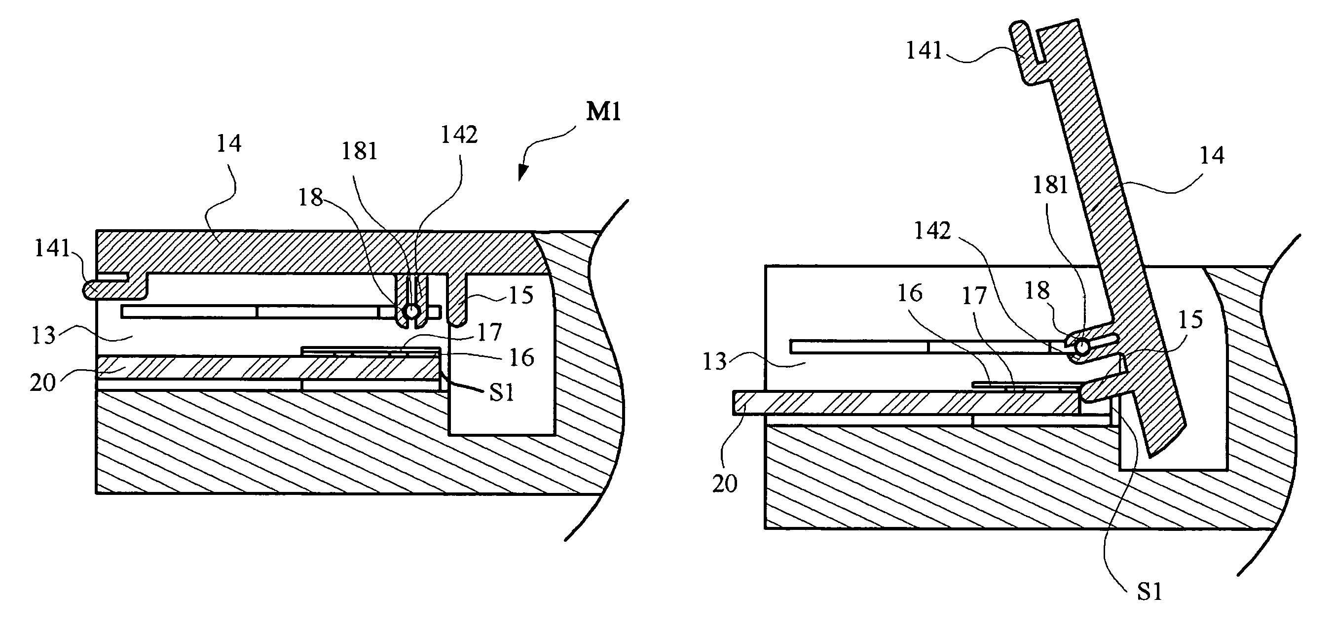
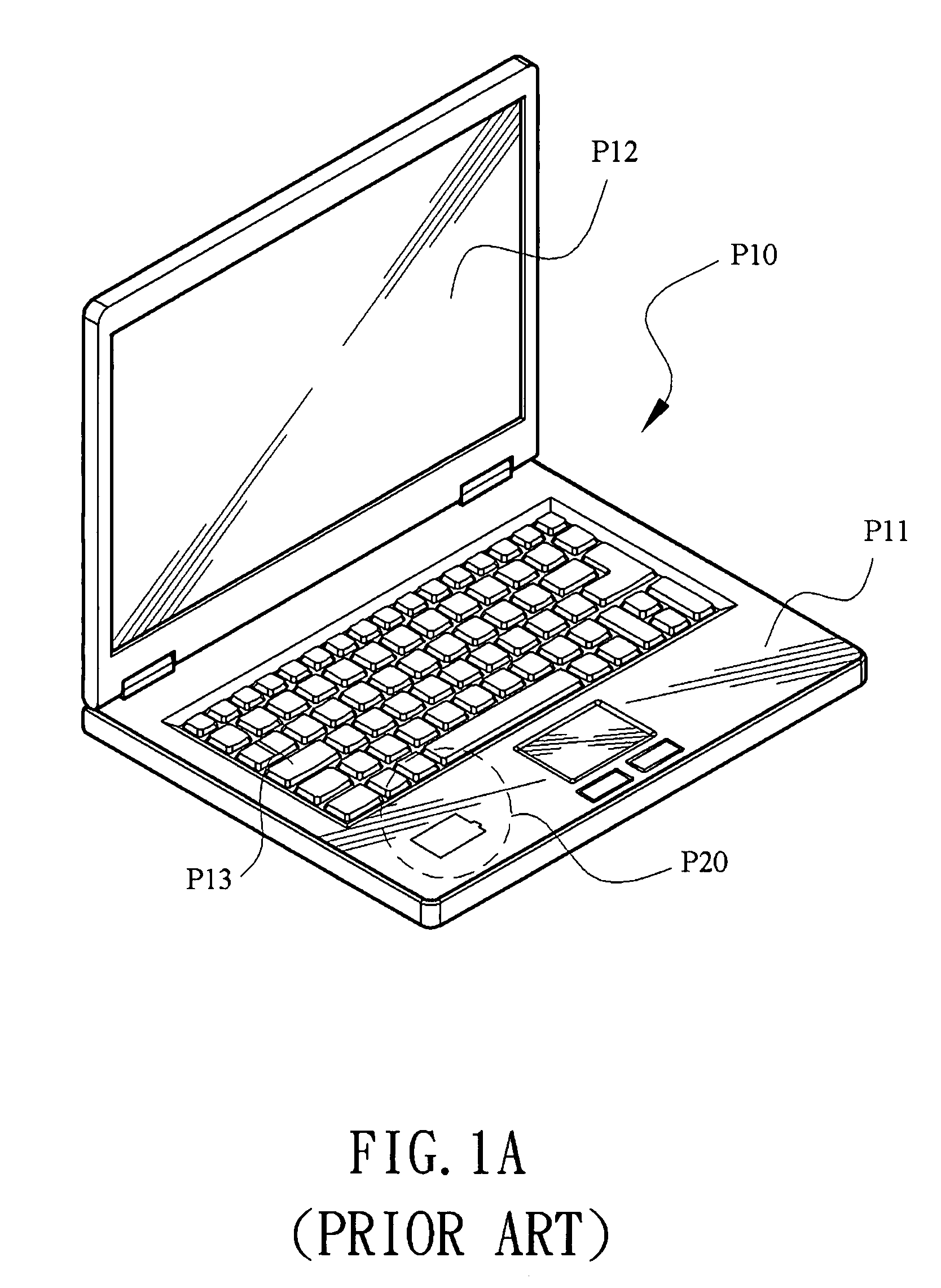
[0021]Referring to FIGS. 2 and 3, a card insertion structure of an electronic device provided by the present invention is shown, which is used to insert a card 20. The electronic device 1 is, but not limited to, a notebook computer, a desktop computer, a mobile phone, a handheld computer or a personal digital assistant. the card insertion structure 10 of the electronic device includes an accommodating groove 11, a first cover 12, a card slot 13, and a second cover 14, wherein the accommodating groove 11 is caved in the electronic device 1, and the first cover 12 is covered on the accommodating groove 11. Referring to FIGS. 4A and 4B, the card slot 13 is formed by depressing in a wall of the accommodating groove 11, and makes the card 20 inserted into an insertion position S1. Herein, the insertion position S1 refers to a position that the card 20 is completely inserted therein and electrically connected to the electronic device 1. In this manner, the electronic device 1 may be used ...

second embodiment

[0025]Further, referring to FIG. 6, following the card insertion structure of the above electronic device, the card insertion structure 10 of the electronic device further includes a power supply element 30 accommodated in the accommodating groove 11, so as to provide power for the operation of the electronic device 1. The first cover 12 may be, but not limited to, formed by extending from the casing of the power supply element 30. Therefore, likewise, when the power supply element 30 is in the accommodating groove 11, the first cover 12 covered thereon catches the second cover 14 to be in the covered position M1, such that the second cover 14 cannot be pivoted when the first cover 12 is in the covered state and even when the first cover 12 is not in the covered state, the second cover 14 is still kept from being pivoted as the power supply element 30 is accommodated in the accommodating groove 11, so as to prevent the card 20 from being ejected arbitrarily. Furthermore, when the se...

third embodiment

[0026]Additionally, following the card insertion structure of the above electronic device, referring to FIG. 7, with regard to the card insertion structure 10 of the electronic device, the first cover 12 is replaced with only one power supply element 30 and is directly accommodated in the accommodating groove 11. That is, without the first cover 12, the power supply element 30 can also be used to provide power for the operation of the electronic device 1. Therefore, in the same operation manner as above, being in the accommodating groove 11, the power supply element 30 catches the second cover 14 to be in the covered position M1 to prevent the second cover 14 from being pivoted and thus avoid the card being ejected arbitrarily. Moreover, when the power supply element 30 is moved out and the second cover 14 is pivoted from the covered position M1 to the card ejection position M2, the pushing member 15 pushes the card 20 to move out of the insertion position S1 as the electronic devic...


PUM


Abstract

A card insertion structure of an electronic device is provided, which includes an accommodating groove caved in the electronic device, a first cover covered on the accommodating groove, a card slot extending from a wall of the accommodating groove, and a second cover pivotally disposed on the electronic device. The card slot is used for inserting a card such as a subscriber identity module (SIM) card, and the first cover catches the second cover to be in a covered position. When the card is to be ejected, the second cover cannot be pivoted unless the first cover is removed first, and the second cover pushes the card to move outwards when being pivoted, thus achieving the purpose of ejecting the card. Furthermore, due to the catch of the first cover, the card cannot be ejected if the second cover is inappropriately pivoted, thereby avoiding damaging the card.

Description

BACKGROUND OF THE INVENTION[0001]1. Field of Invention[0002]The present invention relates to a card insertion structure of an electronic device, and more particularly, to a card insertion structure of an electronic device which prevents the card from being ejected in an incorrect way and can eject the card automatically.[0003]2. Related Art[0004]Currently, in order to combine a notebook computer with a mobile phone in a more convenient way, a space for directly inserting an SIM card of the mobile phone has been designed in the notebook computer, such that the notebook computer acquires multiple functions of using the mobile phone to surf on the Internet, make a call, and even combine the address books of the two, and so on. With regard to the above design, the following design methods are available in the current market. Referring to FIGS. 1A and 1B, a notebook computer with the aforementioned communication functions in the prior art is shown. Standard accessories, such as a display...

Claims


Application Information

Patent Timeline
Patent Type & Authority Patents(United States)
IPC IPC(8): H01R13/62
CPCH01R13/633H04B1/3816H04B1/3818
Inventor LIN, YUN-TANG
Owner INVENTEC CORP
Why Eureka
Try Eureka