Field emission lamp

a field emission lamp and field technology, applied in the field of lamps, can solve the problems of incandescent lamps having a low inability to use luminescence, and most electric energy consumed by incandescent lamps is converted into heat energy, etc., and achieves low energy consumption, high electrical energy utilization ratio, and reduced cost

Active Publication Date: 2008-04-08
BEIJING FUNATE INNOVATION TECH +1
View PDF4 Cites 2 Cited by
  • Summary
  • Abstract
  • Description
  • Claims
  • Application Information

AI Technical Summary

Benefits of technology

[0010]Compared with a conventional field emission lamp, the field emission lamp of any of the described embodiments has the following advantages. Firstly, the field emission lamp does not adopt mercury vapor or other noxious vapor, and thus is safe for humans and environmentally friendly. Secondly, the bulb of the field emission lamp is vacuumized. There is no need for a filling gas, and costs are reduced. Thirdly, the field emission lamp adopts a cold cathode, thereby providing a high electrical energy utilization ratio and low energy consumption.

Problems solved by technology

However, most electric energy consumed by the incandescent lamp is converted into heat energy and cannot be used for luminescence.
In other words, the incandescent lamp has a low electrical energy utilization ratio, and is uneconomical.
This causes excitation of the mercury vapor and subsequent remission.
The mercury vapor is toxic to humans and is environmentally unsafe.
However, adopting inert gases increases the cost of the fluorescent lamp.
Furthermore, the inert gases are apt to leak out, and this results in the fluorescent lamp becoming dim or even failing to luminesce at all.
Moreover, the fluorescent lamp generally adopts a hot cathode, and therefore needs a high working voltage.
As a result, the electric energy utilization ratio of the fluorescent lamp may still be considered to be unsatisfactory.
Secondly, the bulb of the field emission lamp is vacuumized.

Method used


Image

  • Field emission lamp
  • Field emission lamp
  • Field emission lamp

Examples


Embodiment Construction

[0018]Reference will now be made to the drawings to describe preferred embodiments of the present invention in detail.

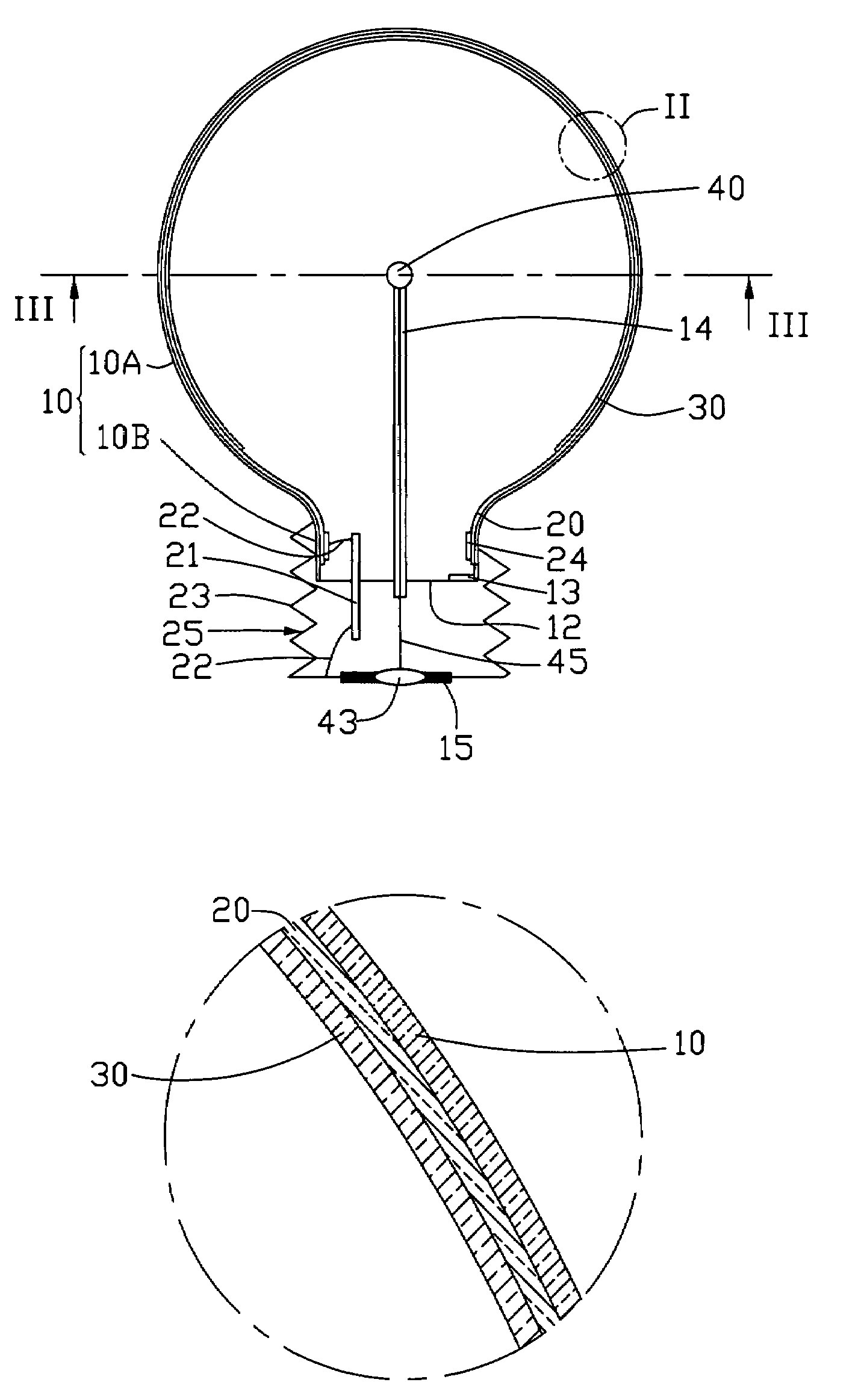
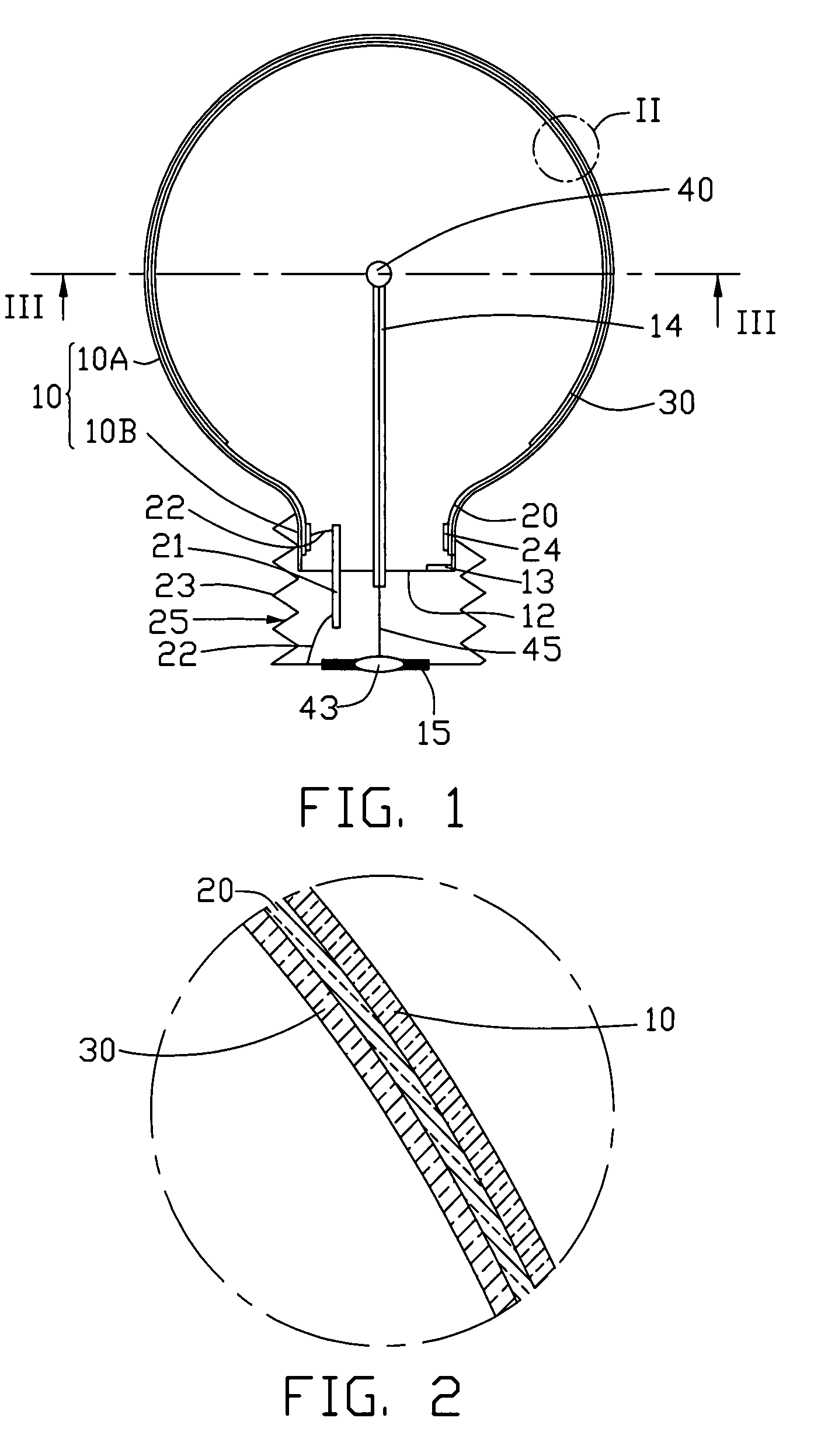
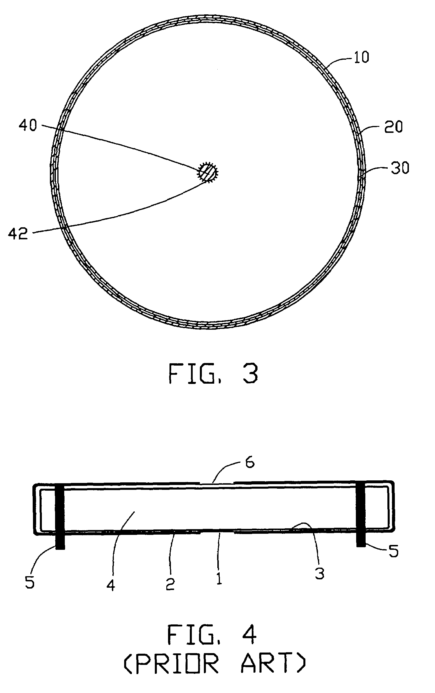
[0019]Referring to FIGS. 1 and 2, a field emission lamp includes: a lamp body of the lamp, for example, a transparent glass bulb 10 having a main portion 10A and a neck portion 10B; a lamp head 25 mated with the neck portion 10B; an anode layer 20 formed on an inner surface (not labeled) of the bulb 10; a fluorescence layer 30 formed on the anode layer 20; a cathode electrode 43 and an anode electrode 23 located at the lamp head; an anode down-lead ring 24 located at the neck portion 10B, the anode down-lead ring 24 engaging with the anode layer 20 and electrically connecting with the anode electrode 23 via an anode down-lead pole 21 and a pair of anode down-leads 22; and an electron emitting cathode positioned in the bulb 10 and engaging with the cathode electrode 43.

[0020]The anode layer 20 is a transparent conductive film, such as an Indium Tin Oxide (ITO) film. T...


PUM


Abstract

A field emission lamp includes: a transparent bulb (10) having a neck portion; a lamp head mated with the neck portion; an anode layer (20) formed on an inner surface of the bulb; a fluorescence layer (30) formed on the anode layer; a cathode electrode (43) and an anode electrode (23) located at the lamp head; an anode down-lead ring (24) located at the neck portion, the anode down-lead ring engaging with the anode layer and electrically connecting with the anode electrode via an anode down-lead pole (21) and a pair of down-leads (22); and an electron emitting cathode positioned in the bulb and engaging with the cathode electrode. The field emission lamp is safe for humans and environmentally friendly, provides a high electrical energy utilization ratio, and has a reduced cost.

Description

BACKGROUND OF THE INVENTION[0001]1. Field of the Invention[0002]The invention relates generally to lamps, and more particularly to the field emission lamps.[0003]2. Description of Related Art[0004]Electrical lamps are virtual necessities in modem daily living, and conventional electrical lamps generally include incandescent lamps and fluorescent lamps. A typical incandescent lamp is simple to manufacture. However, most electric energy consumed by the incandescent lamp is converted into heat energy and cannot be used for luminescence. In other words, the incandescent lamp has a low electrical energy utilization ratio, and is uneconomical.[0005]A conventional fluorescent lamp has a higher electric energy utilization ratio compared to the incandescent lamp. A typical conventional fluorescent lamp generally includes a transparent glass tube, white or colored fluorescent material coated on an inner surface of the transparent glass tube, and mercury vapor filled in the transparent glass t...

Claims


Application Information

Patent Timeline
Patent Type & Authority Patents(United States)
IPC IPC(8): H01J1/02H01J19/00
CPCH01J63/06
Inventor WEI, YANGLIU, PENGSHENG, LEI-MEILIU, LIANGHU, ZHAO-FUGUO, CAI-LINCHEN, PI-JINFAN, SHOU-SHAN
Owner BEIJING FUNATE INNOVATION TECH
Why Eureka
Try Eureka