Modular liquid cooling of electronic assemblies

a technology of electronic assemblies and modules, applied in the field of electronic assemblies, can solve the problems of increasing power consumption in smaller spaces, creating new challenges for system designers,

Inactive Publication Date: 2008-04-08
AMPHENOL CORP
View PDF45 Cites 84 Cited by
  • Summary
  • Abstract
  • Description
  • Claims
  • Application Information

AI Technical Summary

Problems solved by technology

Not only are more components packed into smaller spaces, but also more power is often consumed in smaller spaces.
This increased “power density” creates new challenges for system designers.

Method used


Image

  • Modular liquid cooling of electronic assemblies
  • Modular liquid cooling of electronic assemblies
  • Modular liquid cooling of electronic assemblies

Examples


Embodiment Construction

[0021]As used throughout this document, the words such “comprising,”“including,” and “having” are intended to set forth certain items, steps, elements, or aspects of something in an open-ended fashion. Unless a specific statement is made to the contrary, these words do not indicate a closed list to which additional things cannot be added.

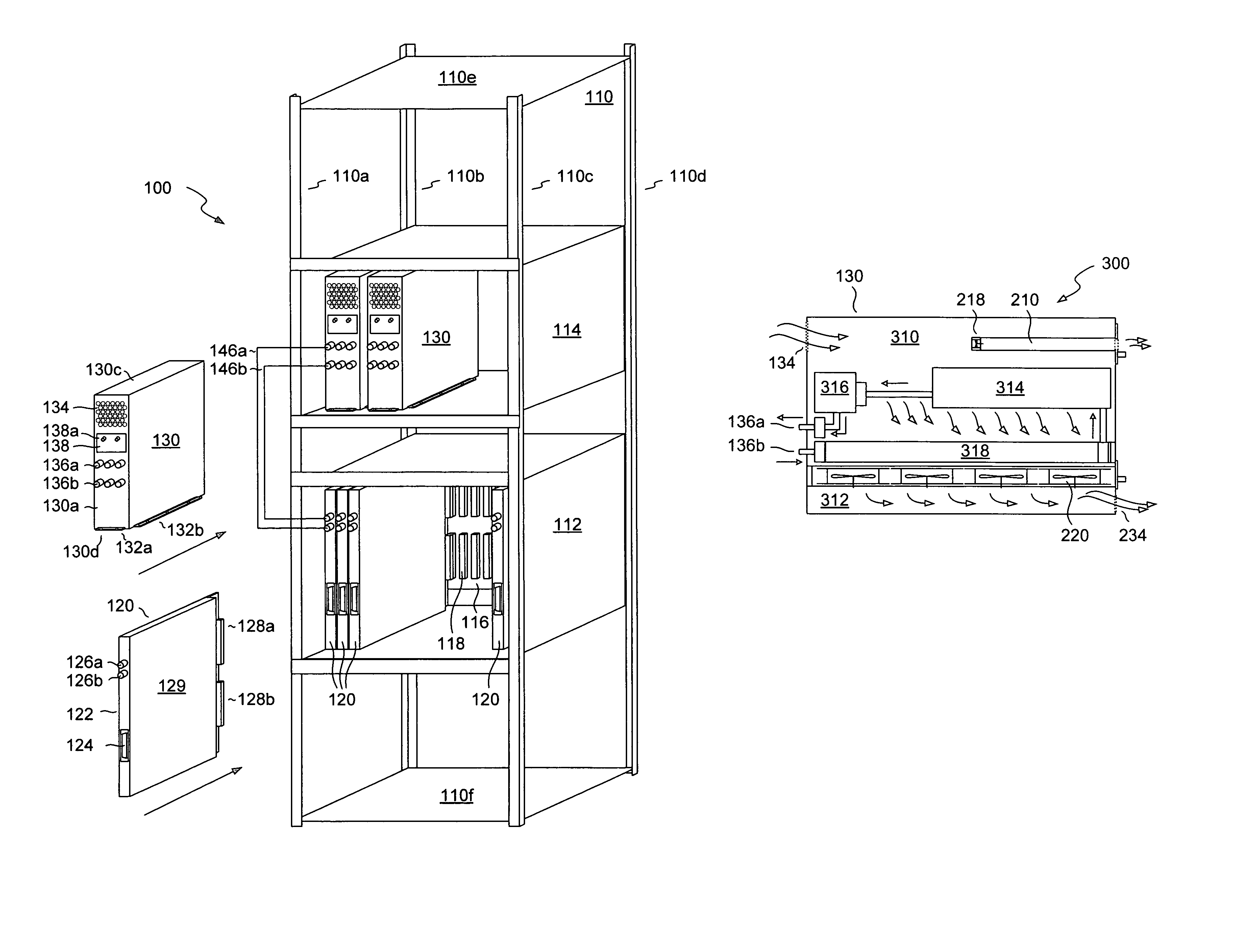
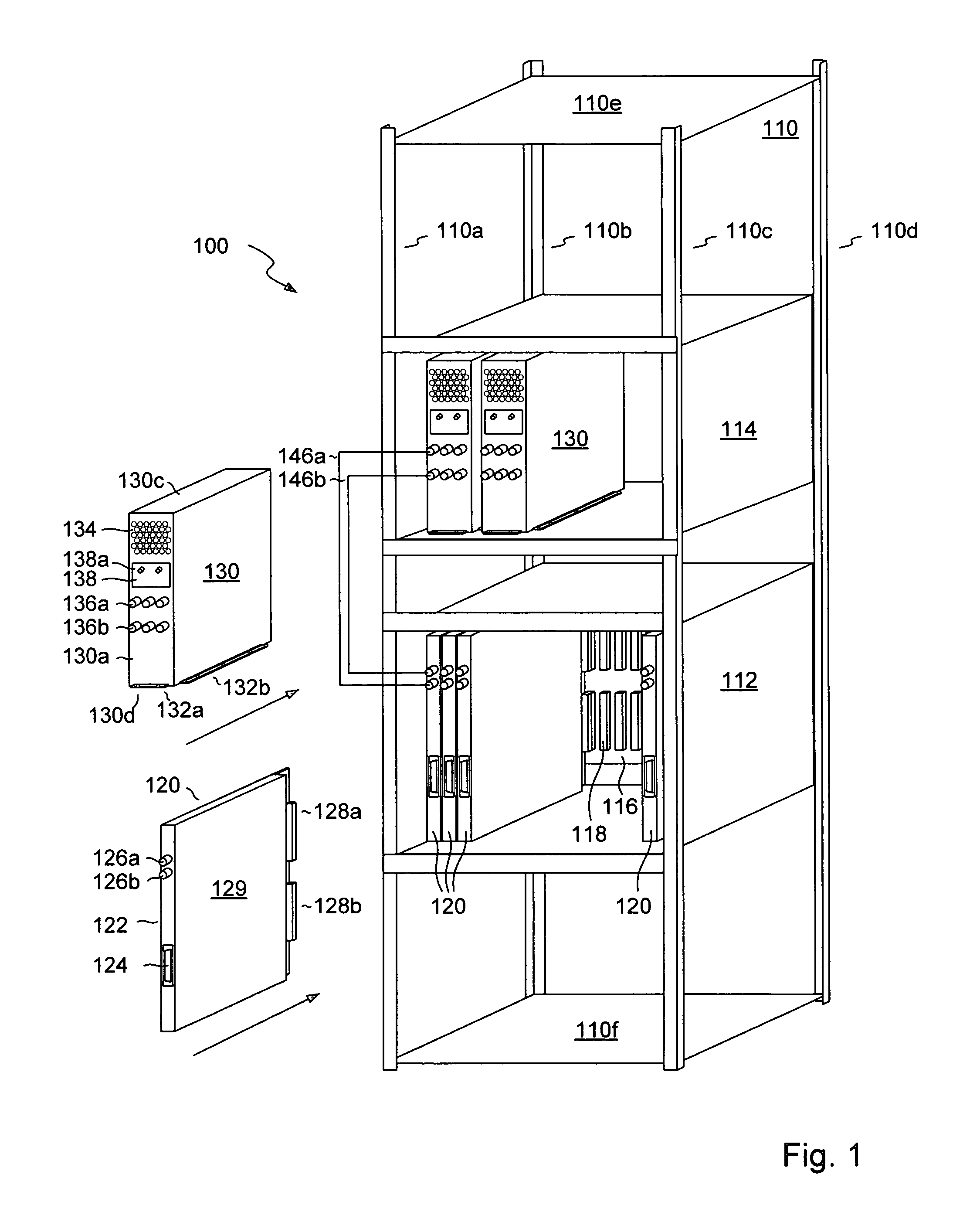
[0022]FIG. 1 shows an illustrative embodiment 100 of an electronic system. The system 100 includes a frame 110, which is preferably a rack, such as a standard 19-inch (48.3 cm) rack. The rack 110 preferably has vertical supports 110a, 110b, 110c, and 110d, a top shelf 110e, and a bottom shelf 110f.

[0023]A card cage 112 is inserted into the rack, where it is preferably attached using bolts. The card cage 112 preferably houses a backplane 116, which has backplane connectors 118. The card cage 112 is at least partially loaded with circuit board assemblies 120, installed side-by-side.

[0024]As shown at the bottom-left of FIG. 1, each circuit board assem...


PUM


Abstract

An electronic system includes an array of electronic assemblies at a first location within a system. An array of liquid cooling assemblies is placed at a second location within the system. Hoses or other liquid transport pathways connect the cooling assemblies to the electronic assemblies, for cooling the electronic assemblies. As more electronic assemblies are added to the system, additional cooling assemblies may be provided to manage the increased thermal demands.

Description

CROSS-REFERENCES TO RELATED APPLICATIONS[0001]Not Applicable.STATEMENT REGARDING FEDERALLY SPONSORED RESEARCH OR DEVELOPMENT[0002]Not Applicable.REFERENCE TO MICROFICHE APPENDIX[0003]Not Applicable.BACKGROUND[0004]1. Field of the Invention[0005]This invention relates generally to electronic assemblies, and, more particularly, to thermal management of electronic assemblies.[0006]2. Description of Related Art[0007]Many modern electronic systems are constructed from circuit board assemblies. As is known, a circuit board assembly includes electronic components that mount to an insulative substrate. Wires or traces are placed on different layers of the substrate to electrically interconnect the components. A circuit board assembly generally includes one or more connectors for attaching the assembly to other parts of an electronic system, and may include multiple tiers of circuit boards connected together.[0008]Circuit board assemblies are typically provided in standard sizes and shapes. ...

Claims


Application Information

Patent Timeline
Patent Type & Authority Patents(United States)
IPC IPC(8): H05K7/20
CPCG06F1/20G06Q20/1235G06Q20/204G07F17/16G06Q30/0641G07F13/025G07F17/0014G06Q20/20G06F2200/201C02F2209/005
Inventor PFAHNL, ANDREAS C.
Owner AMPHENOL CORP
Why Eureka
Try Eureka