Paper supply device and image forming device equipped with same

a technology of paper supply and image forming device, which is applied in the direction of thin material processing, electrographic process apparatus, instruments, etc., can solve the problems of paper jamming and mis-feeding, paper may slip to the side (skew) or float up, and paper may be unable to meet the needs of use, so as to avoid multi-feed problems and/or marks on the paper, prevent skew and floating of paper, and simple construction

Inactive Publication Date: 2008-04-08
KYOCERA DOCUMENT SOLUTIONS INC
View PDF10 Cites 14 Cited by
  • Summary
  • Abstract
  • Description
  • Claims
  • Application Information

AI Technical Summary

Benefits of technology

[0009]An object of the present invention is to provide a paper supply device and an image forming device equipped with same that can prevent skew and floating of the paper with a simple construction when setting the paper, and avoid generating multi-feed problems and / or marks on the paper.
[0010]A paper supply device according to a first aspect of the present invention is a paper supply device for supplying paper to an image forming unit of an image forming device, and comprises a paper supply device main unit, paper storage unit, regulating member, paper supply roller, and a paper shear prevention member. The paper storage unit stores paper and is arranged in the paper supply device main unit. The regulating member regulates the width direction of the paper stored in the paper storage unit. The paper supply roller feeds the paper stored in the paper storage unit to the image forming unit. The paper shear prevention member prevents the paper from shearing and is placed above the paper stored in the paper storage unit. The paper shear prevention member further includes a brush which makes contact with the surface of the paper stored in the paper storage unit, and the brush forms an acute angle against the paper surface in the feed direction of the paper.
[0011]According to the paper supply device according to the first aspect, the load resistance against the paper can be reduced when paper is set in the paper storage unit. Accordingly, setting paper into the paper storage unit is easier and results in improved operability when paper is set. The load resistance against the set paper can be increased in the opposite direction to the feed direction of the paper. Accordingly, the shearing of the paper can be prevented in the opposite direction to the feed direction of the paper resulting in the ability to prevent skew and floating of the paper when regulating in the width direction of the paper by the regulating member.

Problems solved by technology

When regulating the position of the paper stored within the paper supply cassette or loaded into the manual feed paper supply tray, the paper may slip to the side (skew) or float up.
When attempting to feed paper by the paper supply roller in this state, problems are generated including paper jams and mis-feeds caused by the feeding of skewed paper.
However, the conventional paper supply device requires a certain amount of weight when pressing the paper by means of the pressing member, and in particular, when there are only a few sheets set in the manual feed paper supply tray, a large amount of weight is required to press the paper.
Accordingly, problems occur such as multi-feeding of the paper, and marks being produced on the paper due to the strong friction between the paper and the paper supply rollers, because the weight is applied as a load in order to feed the paper by means of the paper supply rollers, and the feeding load is greater at the time of paper supply.
In addition, it will become more difficult for a user to set the paper into the manual feed paper supply tray, and thus reduce usability, because the load resistance between the paper and the pressing member will increase when a user sets paper into the manual feed paper supply tray.

Method used


Image

  • Paper supply device and image forming device equipped with same
  • Paper supply device and image forming device equipped with same
  • Paper supply device and image forming device equipped with same

Examples


embodiment 1

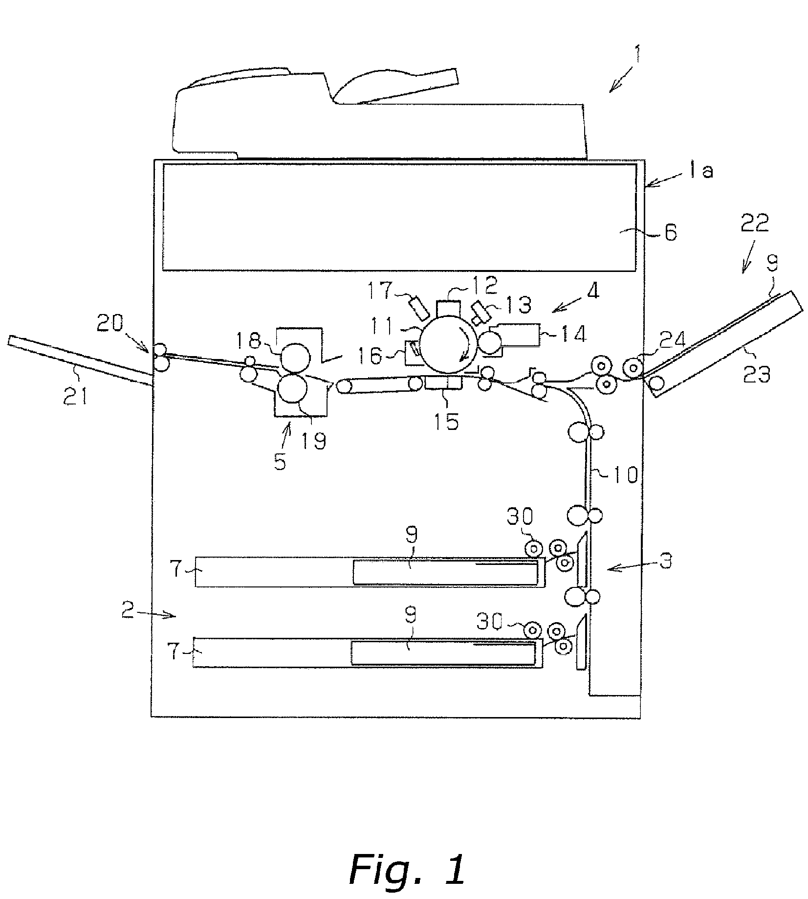
[0034]A detailed description of an embodiment of the present invention is given hereinafter with reference to drawings. FIG. 1 is an outline diagram that shows the overall construction of an image forming device according to the first embodiment of the present invention.

[0035]The image forming device 1 shown in FIG. 1 is a copying machine comprising a paper supply unit 2 which functions as a paper supply device arranged beneath the device main unit 1a, a paper feed unit 3 arranged to the side and above the paper supply unit 2, an image forming unit 4 arranged above the paper feed unit 3, a fusing unit 5 arranged more to the discharge side than the image forming unit 4, and an image reading unit 6 arranged above the image forming unit 4 and fusing unit 5.

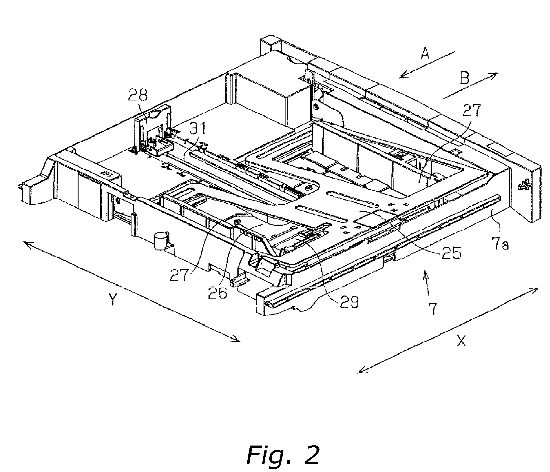
[0036]FIG. 2 shows the construction of the paper supply cassette in the image forming device according to the first embodiment of the present invention. The paper supply unit 2 comprises a plurality (two in the present embodiment) of...

embodiment 2

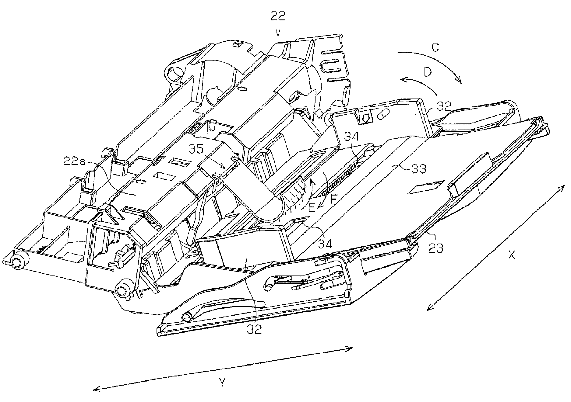
[0052]Next, a description of the second embodiment of the present invention will be provided. FIG. 6 shows a manual feed paper supply device in an image forming device according to a second embodiment of the present invention. FIG. 7 shows a paper shear prevention member in the manual feed paper supply device according to the second embodiment of the present invention. FIG. 8 describes the relationship between the paper and the paper shear prevention member in the manual feed paper supply device according to the second embodiment of the present invention. Moreover, the same reference symbols are used for the constituent elements that are the same as in the first embodiment, and the descriptions thereof are omitted. Further, as the overall construction of the image forming device is the same as in the first embodiment, a detailed description thereof will be omitted.

[0053]As shown in FIG. 6, a paper shear prevention member 37 is arranged on a regulating member 32 for regulating the wi...


PUM


Abstract

A manual paper supply device is equipped with a paper shear prevention member 35 for preventing shear of the paper 9 loaded into the manual feed paper supply tray. A brush 36 is arranged on the paper shear prevention member 35 to make contact with the paper 9; and the brush 36 is arranged to form an acute angle against the paper 9 in the paper 9 feed direction G. Skewing and floating of the paper 9 are prevented accordingly when the paper 9 is set. Further, the generation of multi-feed and marking of the paper 9 is avoided.

Description

BACKGROUND OF THE INVENTION[0001]1. Field of the Invention[0002]The present invention relates to a paper supply device for supplying paper and an image forming device equipped with same.[0003]2. Background Information[0004]Image forming devices such as copying machines, printer devices, and facsimiles, are generally equipped with a paper supply device for supplying paper. These paper supply devices are equipped with a cassette paper supply unit for supplying paper from a paper supply cassette where a plurality of paper is stored, as well as a manual feed paper supply unit for supplying a comparatively small number of sheets. The paper supply devices having these types of cassette paper supply units and manual feed paper supply units are equipped with dedicated paper supply rollers that are exclusively used in each of the cassette paper supply units and manual feed paper supply units. Further, the rotating action of these paper supply rollers sends sheets of paper into the main unit ...

Claims


Application Information

Patent Timeline
Patent Type & Authority Patents(United States)
IPC IPC(8): G03G15/00B65H3/46
CPCB65H1/00G03G15/6514B65H2404/561B65H2404/6942B65H2407/21G03G2215/00561
Inventor YAMAMOTO, KIYONORI
Owner KYOCERA DOCUMENT SOLUTIONS INC
Why Eureka
Try Eureka