Card stack reader, card thereof, card case, method for manufacturing card, game machine using the same, computer-readable storage medium on which game program is recorded

a card stack and card reader technology, applied in the field of card stack readers, can solve the problems of insufficient realism of the card game in the player, liable to doubt the fairness of the card game, and players cannot check the accuracy of the computer-controlled card game, so as to prevent the illegal duplication of the read code, short reading time, and free from damage or stain.

Inactive Publication Date: 2008-04-15
SEGA CORP
View PDF32 Cites 147 Cited by
  • Summary
  • Abstract
  • Description
  • Claims
  • Application Information

AI Technical Summary

Benefits of technology

[0008]An object of the present invention is to provide an improved card stack reader in which the above-described problems are eliminated.
[0009]Another object of the present invention is to provide a card stack reader that reads an image directly from a stack of cards with a short period of reading and does not require a transporting mechanism which causes the cards to be damaged or stained.
[0010]Another object of the present invention is to provide a card that is used by a card stack reader which reads an image directly from a stack of cards with a short period of reading and does not require a transporting mechanism which causes the cards to be damaged or stained.

Problems solved by technology

However, in the conventional card game machine, the card image merely appears on the CRT monitor, which is inadequate for the player to really enjoy the card game or duplicate “live” feelings of the card game.
It does not sufficiently bring the realism of the card game into the player.
The players cannot check the computer-controlled card game for accuracy, and are liable to doubt the fairness of the card game.
When such a mechanism is provided in a card stack reader system, the resulting system becomes large in size, and the normal cards may be damaged or stained.
Furthermore, the period of reading all the normal cards becomes relatively long.

Method used


Image

  • Card stack reader, card thereof, card case, method for manufacturing card, game machine using the same, computer-readable storage medium on which game program is recorded
  • Card stack reader, card thereof, card case, method for manufacturing card, game machine using the same, computer-readable storage medium on which game program is recorded
  • Card stack reader, card thereof, card case, method for manufacturing card, game machine using the same, computer-readable storage medium on which game program is recorded

Examples


first embodiment

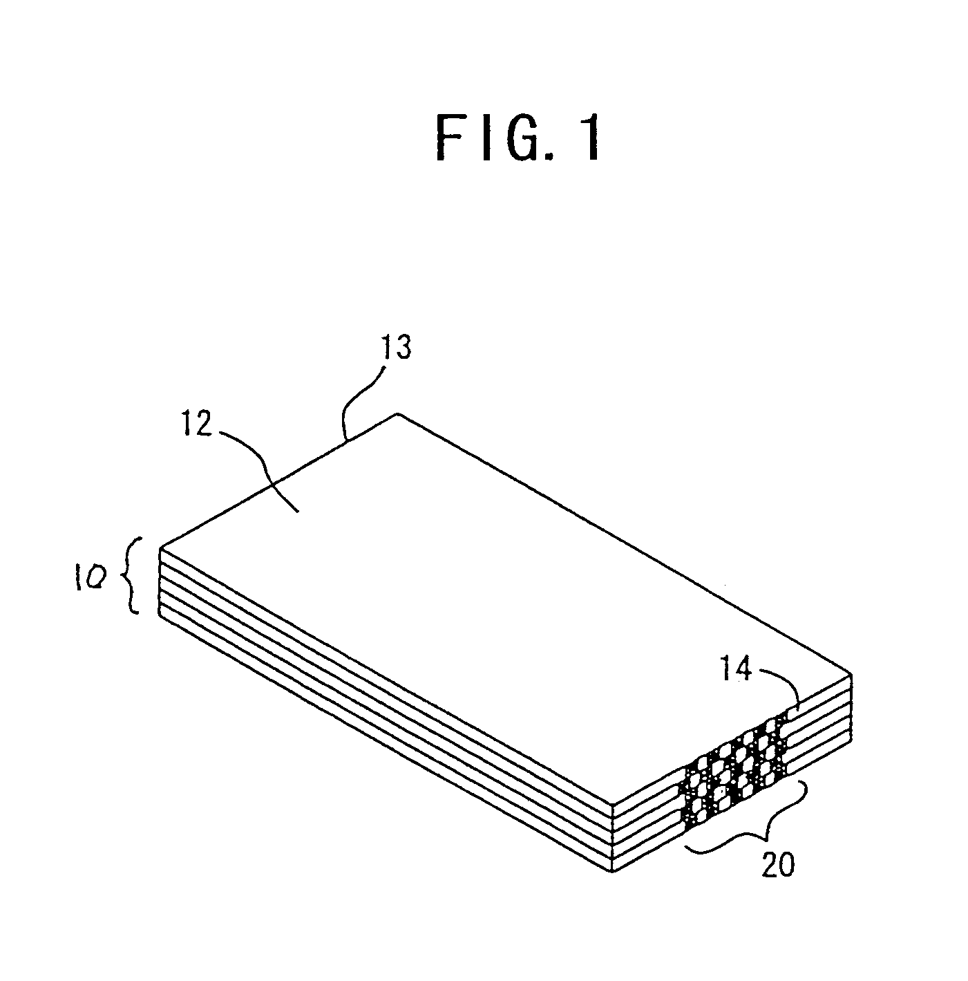
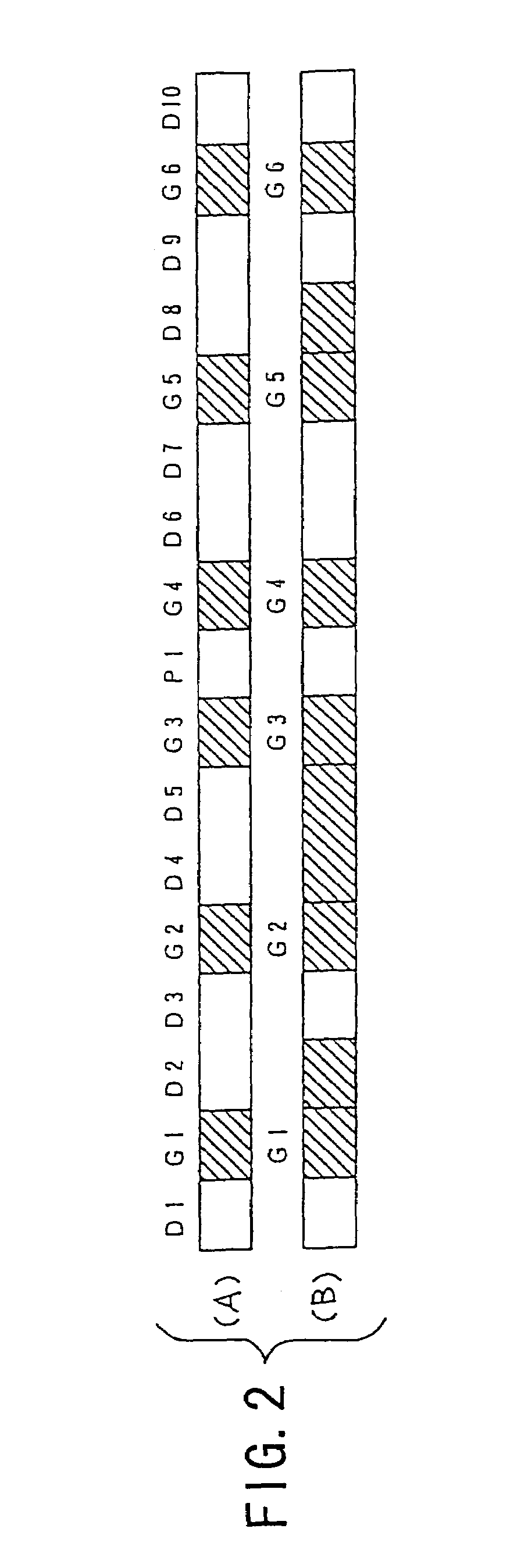
[0097]FIG. 2 shows the format of a read code 20. As shown in FIGS. 2(A) and (B), the read code 20 includes guide bits G1 to G6 (which are indicated by the shaded lines) provided at given positions on the peripheral side edge of the card, data bits D1 to D10 each provided adjacent to one of the guide bits G1 to G6, and a parity bit P1 provided between two of the guide bits G1 to G6. In the present embodiment, the distances of the guide bits G1 to G6 from each of the extreme ends of the peripheral side edge of the card are fixed. Among the data bits D1 to D10 in the read code 20, when a portion of a certain data bit is printed with ink, the corresponding data bit represents the value one, and when a portion of a certain data bit is not printed with ink, the corresponding data bit represents the value zero.

[0098]In the present embodiment, a total value that is indicated by the set of the data bits D1 to D10 of the read code 20 of each card 12 correspond to a graphic pattern on the fron...

second embodiment

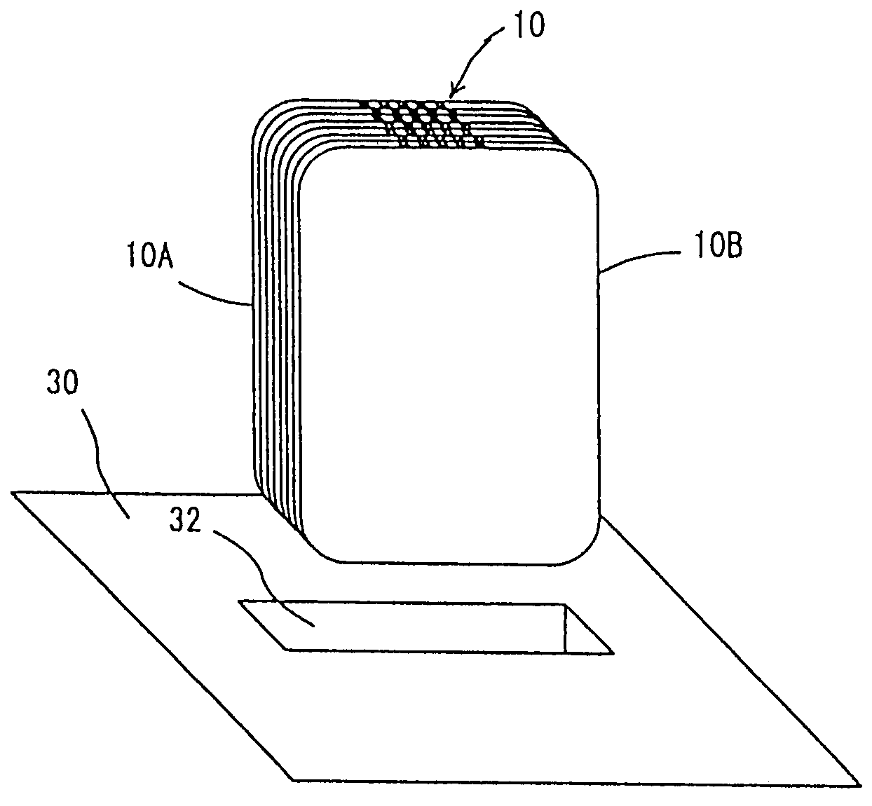
[0113]FIG. 8 shows the card stack reader of the present invention. As shown in FIG. 8, in the card stack reader of the present embodiment, the card stack 10 is provided with the four sides of the cards being aligned. An image sensor 60 is provided to straightly confront the peripheral side portion 14 of the card stack 10 where the read code is printed to each card 12. A dichroic mirror 62 is provided between the card stack 10 and the image sensor 60, such that the surface of the dichroic mirror 62 is inclined at 45 degrees to the optical axis of the image sensor 60. A UV lamp 64 is provided so that the optical path of a UV light emitted by the UV lamp 64 crosses the optical axis of the image sensor 60 at right angles. A reflector plate 66 is attached to the UV lamp 64 in order to direct the UV light of the UV lamp 64 toward the dichroic mirror 62. The reflector plate 66 serves to prevent the scattering of the UV light in different directions than the direction toward the dichroic mi...

third embodiment

[0118]FIG. 9 shows the card stack reader of the present invention. As shown in FIG. 9, in the card stack reader of the present embodiment, the card stack 10 is held with the two sides of the cards being aligned and the remaining two sides being inclined. As shown in FIG. 10, the card 12 has a read code 20 provided on a front surface of the car along the peripheral side edge 14 thereof. The read code 20 is similar to the embodiment of FIG. 7. After the read code 20 is printed to a portion adjacent to the peripheral side edge of the card 12 on the front surface thereof, the card 12 is cut along a straight line passing through the coded-printed portion to form the peripheral side edge of the card 12 where the read code 20 is printed.

[0119]In the card stack reader of the present embodiment, an image sensor 60 is provided to straightly confront the inclined side surface of the card stack 10 that are formed by the peripheral side edges of the cards 12 where the read code 20 is printed to ...


PUM


Abstract

The present invention relates to a card stack reader, a card thereof, a card case, a method for manufacturing the card, a game machine using the same, and a computer-readable storage medium on which a game program is recorded. The card stack reader comprises an imaging unit which reads an image from a peripheral side portion of a stack of cards, each card having a read code along a peripheral side edge thereof, the read code identifying the card, and a code recognizing unit which recognizes the read code of each card from the image read by the imaging unit.

Description

[0001]This application is a continuation of application Ser. No. 09 / 890,663, filed on Apr. 4, 2002, now abandoned which is hereby incorporated by reference in its entirety.FIELD OF THE INVENTION[0002]The present invention relates to a card stack reader, a card thereof, a card case, a method for manufacturing a card, a game machine using the same, and a computer-readable storage medium on which a game program is recorded. The present invention relates to a card stack reader which reads an image from a stack of cards, a card used in the card stack reader, a card case containing the stack of cards, a method for manufacturing the card, a game machine using the same, and a computer-readable storage medium on which a game program is recorded.BACKGROUND OF THE INVENTION[0003]For example, a card game machine that can play a card game, such as poker, blackjack or a fortunetelling game, is known. In the card game machine, a displayed image of plural cards appears on the CRT (cathode ray tube)...

Claims


Application Information

Patent Timeline
Patent Type & Authority Patents(United States)
IPC IPC(8): A63F9/24A63F1/12G06K7/10G06K7/14G06K7/00A63F1/14G06F17/00G06F19/00A63F13/00A63F13/33A63F13/69B42D25/00B42D25/36B42D25/378B42D25/387G06K1/12G06K7/12G06K17/00G06K19/00G06K19/06G06Q50/00G06Q50/10
CPCG06K7/10
Inventor YOSHIDA, TOSHIKAZUSHIBA, HIDENORIKAJI, TOSHIYUKIYAMAUCHI, TAKAOKATO, FUMIHIRONISHINO, AKIRAOHARA, TORUTERADA, TAKAHARU
Owner SEGA CORP
Why Eureka
Try Eureka