Chemical mechanical polishing pad and chemical mechanical polishing method

a technology of mechanical polishing pad and mechanical polishing method, which is applied in the direction of lapping machines, manufacturing tools, metal working apparatuses, etc., can solve the problems of greatly affecting the polishing effect, and achieve the effect of excellent in-plane uniformity in the amount of polishing on the surface and high polishing ra

Active Publication Date: 2008-04-15
JSR CORPORATIOON
View PDF15 Cites 33 Cited by
  • Summary
  • Abstract
  • Description
  • Claims
  • Application Information

AI Technical Summary

Benefits of technology

[0007]It is an object of the present invention which has been made in view of the above situation to provide a chemical mechanical polishing pad which has a high polishing rate and excellent in-plane uniformity in the amount of polishing of the surface to be polished even when the amount of an aqueous dispersion for chemical mechanical polishing is made small as well as a chemical mechanical polishing method.
[0013]According to the present invention, there are provided a chemical mechanical polishing pad which has a high polishing rate and excellent in-plane uniformity in the amount of polishing of the surface to be polished even when the amount of an aqueous dispersion for chemical mechanical polishing is made small and a chemical mechanical polishing method using the polishing pad.

Problems solved by technology

It is known that the polishing result is greatly affected by the shape and properties of the chemical mechanical polishing pad in this chemical mechanical polishing.
However, the above publication presents some groove design ideas conceivable from the above concept and does not give any specific guide to find which groove pattern is actually useful in the real production scene.
However, there is unknown a prior art which investigates the design of grooves so as to supply the aqueous dispersion to the entire surface of the polishing surface of the pad efficiently and achieve a high polishing rate and the high uniformity of the polished surface even when the amount of the aqueous dispersion for chemical mechanical polishing is made small.

Method used


Image

  • Chemical mechanical polishing pad and chemical mechanical polishing method
  • Chemical mechanical polishing pad and chemical mechanical polishing method
  • Chemical mechanical polishing pad and chemical mechanical polishing method

Examples


example 1

(1) Manufacture of Chemical Mechanical Polishing Pad

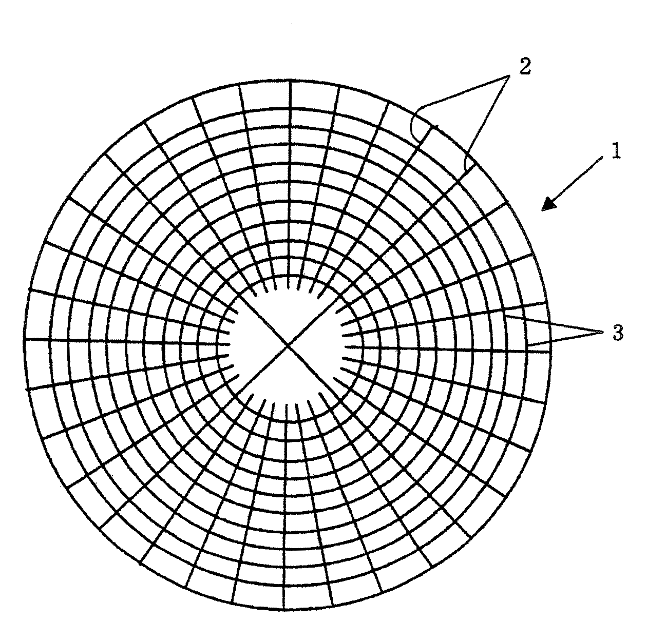
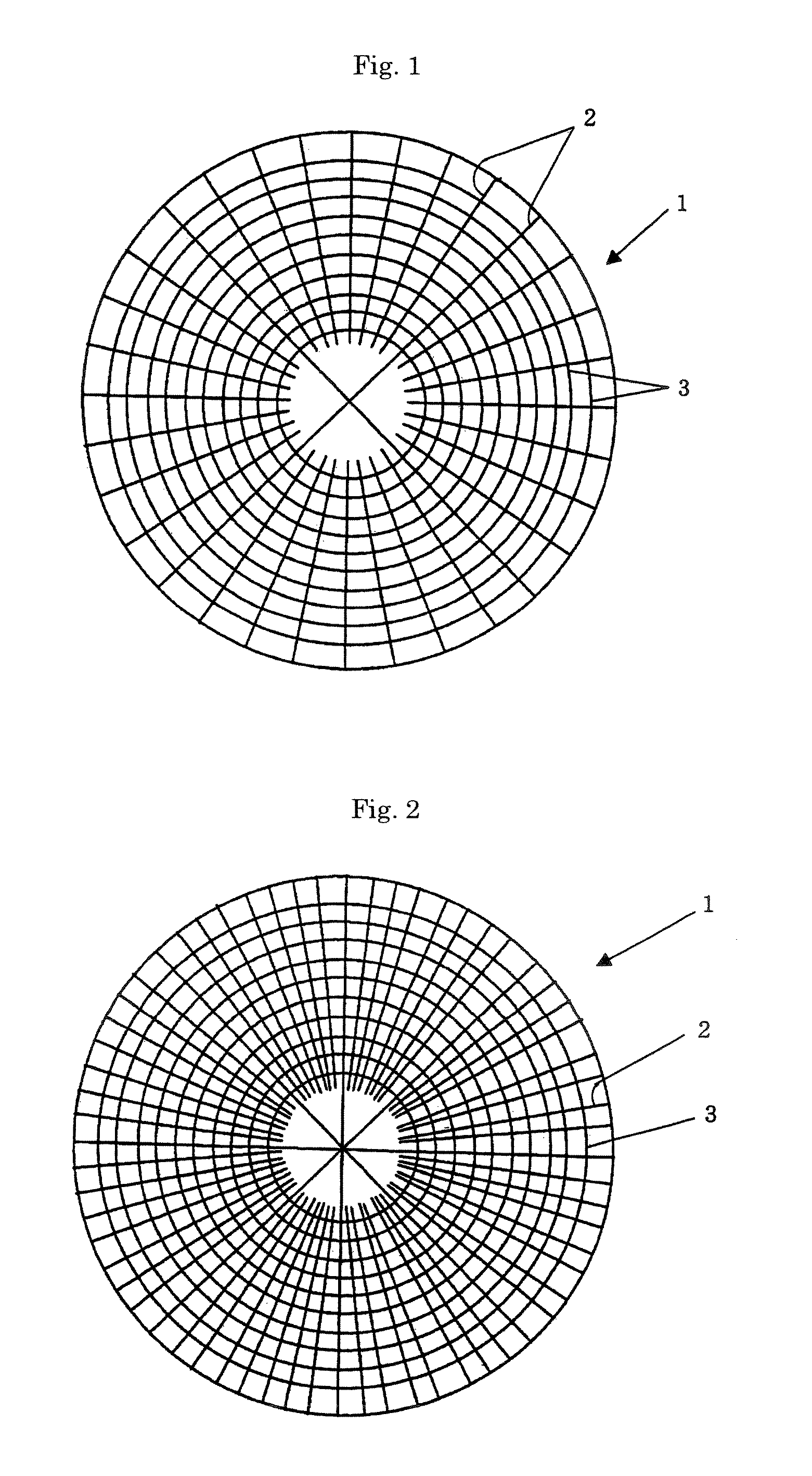
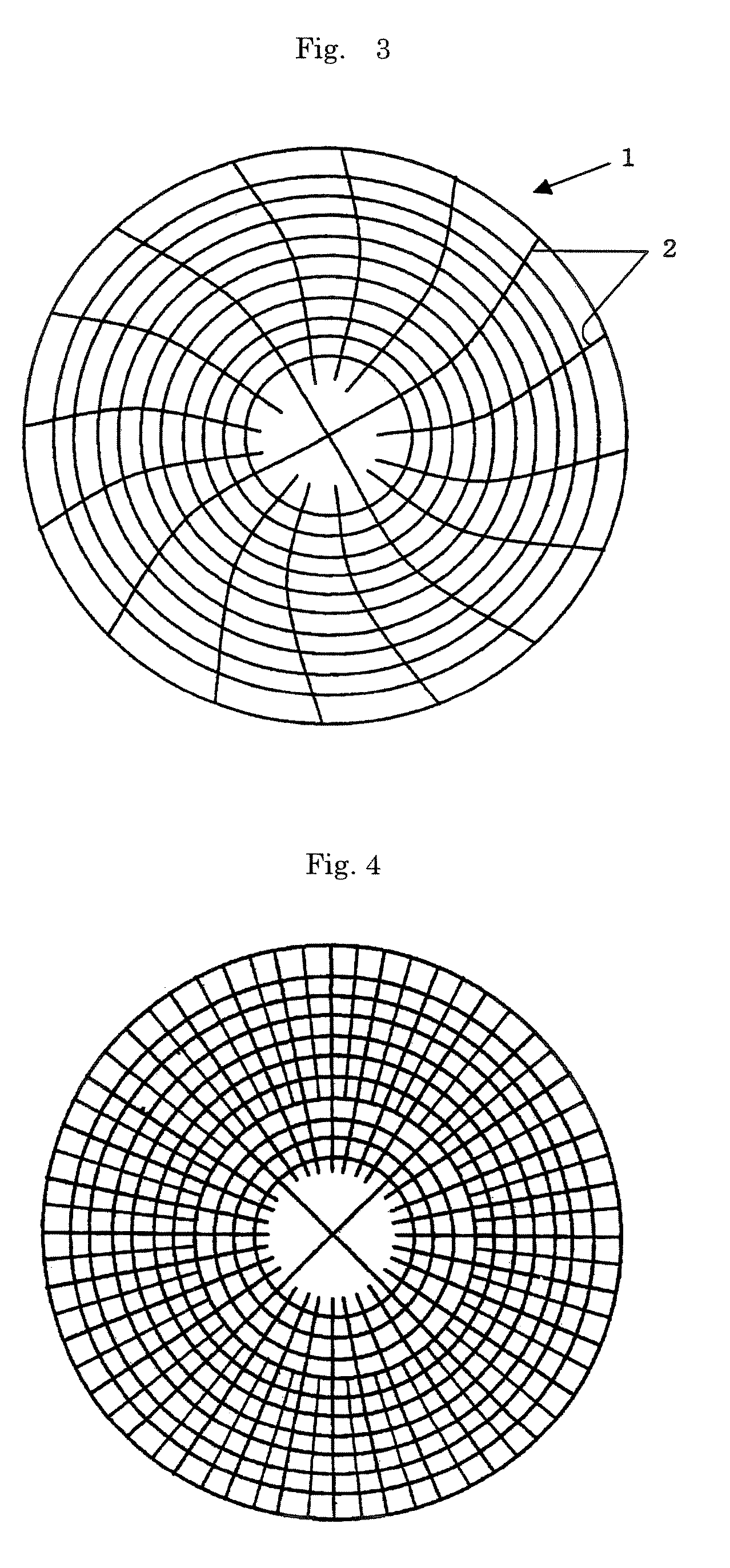
[0099]80 parts by volume (equivalent to 72 parts by mass) of 1,2-polybutadiene (manufactured by JSR Corporation, trade name of “JSR RB830”) which would be crosslinked to become a water-insoluble matrix and 20 parts by volume (equivalent to 28 parts by mass) of β-cyclodextrin (manufactured by Bio Research Corporation of Yokohama, trade name of “Dexy Pearl β-100”, average particle diameter of 20 μm) as water-soluble particles were kneaded together by an extruder set at 160° C. Thereafter, 0.24 part by mass of dicumyl peroxide (manufactured by NOF Corporation, trade name of “Percumyl D”) was added to and kneaded with the above kneaded product at 120° C. to obtain a pellet. The resulting kneaded product was then heated in a metal mold at 170° C. for 18 minutes to be crosslinked so as to obtain a disk-like molded product having a diameter of 508 mm and a thickness of 2.8 mm. Concentrically circular grooves having a width of 0.5 mm, a pi...

example 13

(1) Polishing Test on Copper (Cu) Film Without a Pattern

[0116]A chemical mechanical polishing pad manufactured in the same manner as in Example 1 was set on the platen of the “Mirra / Mesa” polishing machine (of Applied Materials Inc.) to polish a wafer having a copper film without a pattern (a copper film having a thickness of 15,000 Å on an 8-inch silicon substrate having a thermally oxidated film) under the following conditions.[0117]Head revolution: 103 rpm[0118]Platen revolution: 97 rpm[0119]Head pressure: 3 psi[0120]flow rate of aqueous dispersion for chemical mechanical polishing: 100 ml / min[0121]Polishing time: 1 minute

[0122]An aqueous dispersion for chemical mechanical polishing having a pH of 2.5 and containing 1.0 mass % of silica, 0.5 mass % of malic acid, 7.0 mass % of hydrogen peroxide (concentration of 30 mass %) and 0.2 masse of benzotriazole was used. The flow rate of the aqueous dispersion for chemical mechanical polishing used in this example was about half of the s...

example 25

(1) Manufacture of Chemical Mechanical Polishing Pad

[0131]95 parts by volume (equivalent to 92.5 parts by mass) of a mixture obtained by dry blending together 30 parts by mass of polystyrene (manufactured by PS Japan Corporation, trade name of “HF55”) and 70 parts by mass of 1,2-polybutadiene (manufactured by JSR Corporation, trade name of “JSR RB830”) and 5 parts by volume (equivalent to 7.5 parts by mass) of β-cyclodextrin (manufactured by Bio Research Corporation of Yokohama, trade name of “Dexy Pearl β-100”) were kneaded together at 150° C. and 120 rpm by an extruder heated at 120° C. Thereafter, 0.12 part by mass (equivalent to 0.03 part by mass in terms of pure dicumyl peroxide) of “Percumyl D40” (trade name, manufactured by NOF Corporation, containing 40 mass % of dicumyl peroxide) was added to and kneaded with the above kneaded product at 120° C. and 60 rpm. The resulting kneaded product was then heated in a metal mold at 175° C. for 12 minutes to be crosslinked so as to obt...


PUM

PropertyMeasurementUnit
distanceaaaaaaaaaa
widthaaaaaaaaaa
flow rateaaaaaaaaaa

Abstract

A chemical mechanical polishing pad of the present invention has the following two groups of grooves on the polishing surface: (i) a group of first grooves intersect a single virtual straight line extending from the center toward the periphery of the polishing surface and have a land ratio represented by the following equation of 6 to 30: Land ratio=(P−W)÷W (where P is the distance between adjacent intersections between the virtual straight line and the first grooves, and W is the width of the first grooves); and (ii) a group of second grooves extend from the center portion toward the peripheral portion of the polishing surface and consist of second grooves which are in contact with one another in the area of the center portion and second grooves which are not in contact with any other second grooves in the areas of the center portion. The chemical mechanical polishing pad of the present invention has a high polishing rate and excellent in-plane uniformity in the amount of polishing of the surface to be polished even when the amount of an aqueous dispersion for chemical mechanical polishing is made small.

Description

FIELD OF THE INVENTION[0001]The present invention relates to a chemical mechanical polishing pad and a chemical mechanical polishing method.DESCRIPTION OF THE PRIOR ART[0002]In the manufacture of a semiconductor device, chemical mechanical polishing (generally abbreviated as CMP) is now often used as a polishing technique capable of forming an extremely flat surface for a silicon substrate or a silicon substrate having wirings and electrodes thereon. Chemical mechanical polishing is a technique for polishing by letting an aqueous dispersion for chemical mechanical polishing (aqueous dispersion containing abrasive grains dispersed therein) flow down over the surface of a chemical mechanical polishing pad while the polishing pad and the surface to be polished are brought into slide contact with each other. It is known that the polishing result is greatly affected by the shape and properties of the chemical mechanical polishing pad in this chemical mechanical polishing. A wide variety ...

Claims


Application Information

Patent Timeline
Patent Type & Authority Patents(United States)
IPC IPC(8): B24D11/00B24B37/26B24B37/30B24D99/00
CPCB24B37/26B24B37/30B24B37/00
Inventor NISHIMURA, HIDEKISHIMIZU, TAKAFUMIKURIYAMA, KEISUKETSUJI, SHOEI
Owner JSR CORPORATIOON
Why Eureka
Try Eureka