Cavity embedded antenna

a technology of embedded antennas and antennas, which is applied in the direction of antennas, antenna details, antenna adaptation in movable bodies, etc., can solve the problems of preventing the antenna from operating properly, affecting the operation of the antenna, and putting the upper frequency limit, so as to reduce the cost of the nested antenna

Inactive Publication Date: 2008-04-15
BAE SYST INFORMATION & ELECTRONICS SYST INTERGRATION INC
View PDF6 Cites 15 Cited by
  • Summary
  • Abstract
  • Description
  • Claims
  • Application Information

AI Technical Summary

Problems solved by technology

Pushing the upper frequency limit is a problem while maintaining the low frequency cut off.
There is a serious problem if one were to try to extend the upper limit of a wide band embedded meander line loaded antenna in terms of its radiation pattern.
While the desired radiation pattern from such an antenna would be a loop type pattern or in general omni-directional, when the depth of the cavity is increased to lower the low frequency cut off of the antenna, there is a significant null in the radiation pattern at the higher frequencies which is normal to or perpendicular to the face of the antenna.
What this means is that when trying to devise an ultra wide band antenna, the null in the direction perpendicular to the face of the antenna prevents omni directional radiation patterns and thus prevents the antenna from operating properly when it is directly above either a radiating source or when the antenna is used as a transmitting antenna to project energy downwardly in the direction of the null of the antenna pattern.
While meander line structures have been utilized in cavity-embedded embodiments as described above, it will be appreciated that the meander lines themselves, while permitting a broadband miniaturized antenna, are nonetheless costly and relatively difficult to manufacture, especially in quantity.
The result is that heretofore cavity-embedded antennas have not been provided with notches or slot line structures.

Method used


Image

  • Cavity embedded antenna
  • Cavity embedded antenna
  • Cavity embedded antenna

Examples


Embodiment Construction

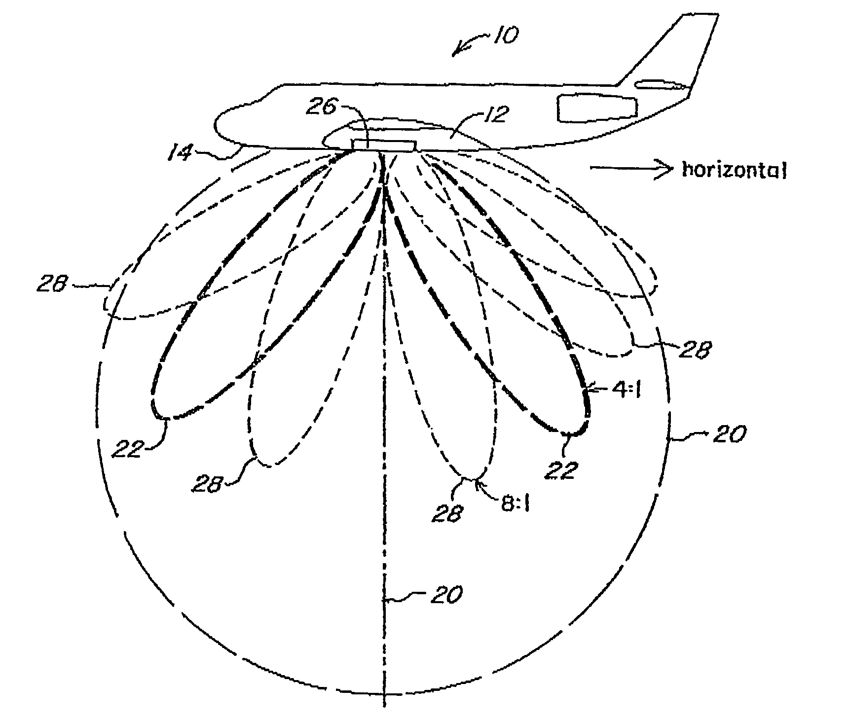
[0062]Referring now to FIG. 1, in one application for an ultra wide band antenna, an aircraft 10 carries an antenna 12 on the under surface 14 thereof, with purpose of the antenna to either transmit energy toward the surface of the earth or to receive radio frequency energy generated at the surface of the earth.

[0063]There are a number of things that are highly desirable in such an application. First, the antenna itself should be embedded within the fuselage of the aircraft so as to minimize wind resistance. Secondly, the antenna should be a small as possible so as to take up as little real estate as possible on the aircraft. This is because of the already cluttered environment due to the multitasking of the aircraft. Thirdly, the antenna pattern should have a loop type antenna pattern which in some cases resembles half of a dipole antenna pattern, but importantly has a significant portion of the lobe extent in the horizontal direction as well as the vertical direction.

[0064]Most im...


PUM


Abstract

A nested cavity embedded loop mode antenna is provided with an ultra wide band response by nesting individual embedded cavity meander line loaded antenna modules, with the meander lines coupled to a ground plane plate either capacitively or directly so as to provide as much as a 27:1 ratio of high frequency to low frequency cutoff. The nested meander line structure is exceptionally compact and eliminates the problem of a null in the antenna radiation pattern perpendicular to the face of the antenna, thus to provide a loop type antenna pattern at all frequencies across which the antenna is to be operated. The use of the nested meander line configuration provides a flush mount for the antenna having a footprint associated with the larger of the meander line cavities and thus the lowest frequency of operation, the nesting precluding the necessity of providing separate side-by-side meander line loaded antennas which would increase the real estate required. Additionally, a shunted slotline embodiment of the cavity-embedded antenna substitutes shunted slots for meander lines to provide for a low-cost wide bandwidth cavity-embedded antenna.

Description

CROSS REFERENCE TO RELATED APPLICATION[0001]This application is related to U.S. application Ser. No. 10 / 405,147 filed Apr. 3, 2003, now U.S. Pat. No. 6,828,947.FIELD OF INVENTION[0002]This invention relates to cavity-embedded antennas and more particularly to a transmission line loaded antenna configuration for providing ultra wide bandwidth.BACKGROUND OF THE INVENTIONMeander Line Loaded Antennas[0003]As described in U.S. patent application Ser. No. 10 / 251,131, filed Sep. 20, 2002 by John T. Apostolos assigned to the assignee hereof and incorporated herein by reference, a wide band meander line antenna is configured to be flush mounted to a conductive surface serving as a ground plane by embedding the meander line components within a conductive cavity surrounded at its top edge by the ground plane. This is done with the antenna looking out of the cavity recessed in the surface. By permitting flush mounting of a meander line antenna, not only can the antenna dimensions be minimized d...

Claims


Application Information

Patent Timeline
Patent Type & Authority Patents(United States)
IPC IPC(8): H01Q1/42H01Q5/00H01Q5/357H01Q7/00H01Q21/30
CPCH01Q7/00H01Q5/357H01Q21/30
Inventor APOSTOLOS, JOHN T.BALL, RICHARD C.HEDGES, STEPHEN A.
Owner BAE SYST INFORMATION & ELECTRONICS SYST INTERGRATION INC
Why Eureka
Try Eureka