Smart instrument tray RFID reader

a technology of instrument tray and reader, which is applied in the direction of instruments, prostheses, burglar alarm mechanical actuation, etc., can solve the problems of overly reliant on human interpretation for performing the necessary functions, surgical instruments that suffer wear and tear, and eventually reach the end of their life cycle, so as to reduce handling costs and accurate and rapid tracking of instruments

Active Publication Date: 2008-04-22
WARSAW ORTHOPEDIC INC
View PDF58 Cites 349 Cited by
  • Summary
  • Abstract
  • Description
  • Claims
  • Application Information

AI Technical Summary

Benefits of technology

[0014]Thus, there exists a need to provide an inventory management system for surgical instruments and surgical trays that reduces handling costs and provides accurate and rapid tracking of instruments over their lifecycle.
[0015]Embodiments of the present invention mitigate or solve the above-identified limitations in known solutions, as well as other unspecified deficiencies in known solutions. A number of advantages associated with various embodiments of the present invention are readily evident to those skilled in the art, including economy of design and resources, transparent operation, cost savings, etc. Various exemplary embodiments according to the method and apparatus of the present invention allow for lower handling costs of surgical instruments, increase the accuracy of the verification process of data pertaining to each instrument with a reduction of human contact, and provide real-time data collection resulting in fast data acquisition, which ultimately speeds up inventory updating of such instruments.

Problems solved by technology

Over time, and through ordinary usage, as well as due to the sterilization process, surgical instruments suffer wear and tear and eventually reach the end of their life cycle.
Also, due to the fact that they are constantly moved from the operating room to sterilization, to storage, and back to the operating room, various instruments on a given tray may become lost, or unrelated instruments from other trays may be added.
Existing methods for performing these necessary functions are overly reliant on costly human interpretation.
As with any human inspection process, the results are limited by the skill and accuracy of the person doing the inspecting.
Usually, these labels are not machine readable, but rather require human interpretation.
There are some restrictions to bar codes, however, that limit their application to surgical instruments and trays.
Bar codes are limited in size by resolution limitations of bar code scanners, and the amount of information that the symbols can contain is limited by the physical space constraints of the label.
Therefore, some objects may be unable to accommodate bar code labels because of their size and physical configuration.
Another limitation of bar code readers is that they require line of sight in order to read the reflection pattern from a bar code.
As labels become worn or damaged, and they can no longer be read with the bar code scanner.
This is particularly likely in the field of surgical instrument trays because of the harsh conditions the labels must undergo during sterilization.
Also, because a person operating the bar code scanner must physically orient either the scanner or the product to achieve line of sight on each item being scanned, items must be scanned one at a time resulting in prolonged scan time.
In addition, because bar code scanning requires the operator to handle each instrument in order to scan it, a potential safety problem is created.
Soiled instruments pose a biohazard because they may have come in contact with bodily fluids, and often have sharp edges.
Therefore, direct human contact either pre or post sterilization may be problematic.
Another limitation of bar code labels is that they are static.
Due in part to a relative increase in cost over equivalent bar code-based systems, RFID tags were originally used only on items of sufficiently high value to justify their use or in environments where bar coding was not possible such as anti theft protection.

Method used


Image

  • Smart instrument tray RFID reader
  • Smart instrument tray RFID reader
  • Smart instrument tray RFID reader

Examples


Embodiment Construction

[0032]The following description is intended to convey a thorough understanding of the invention by providing specific embodiments and details involving automating and adding value to medical and surgical instruments, and instrument kits. It is understood, however, that the invention is not limited to these specific embodiments and details, which are exemplary only. It further is understood that one possessing ordinary skill in the art, in light of known systems and methods, would appreciate the use of the invention for its intended purposes and benefits in any number of alternative embodiments, depending upon specific design and other needs.

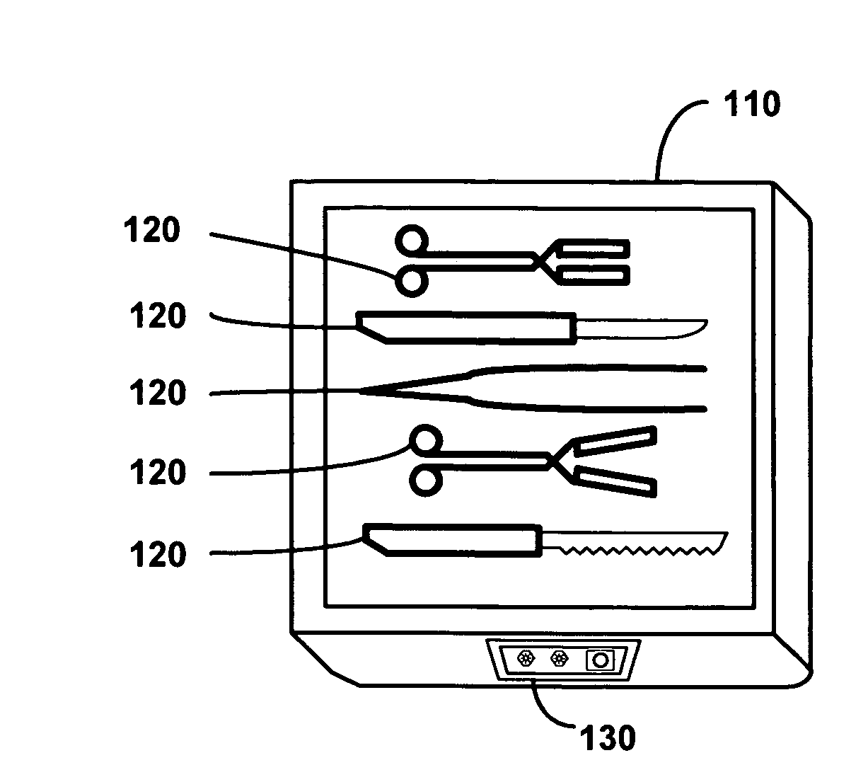
[0033]Referring to FIG. 1, a surgical instrument tray 110 and a plurality of surgical instruments 120 are illustrated in accordance with one exemplary embodiment of this invention. As shown in FIG. 1, the surgical instrument tray 110 comprises a box-like structure having a hollowed body and a roughly planar top surface surrounded on its perimeter...


PUM


Abstract

A radio frequency identification (RFID) workstation reader for RFID-enabled surgical instruments and surgical instrument trays and a method of using a RFID workstation reader to read RFID-enabled surgical instruments and surgical instrument trays is disclosed. The method, apparatus, and system enable individual instruments or a surgical instrument tray containing several surgical instruments to be quickly and efficiently inventoried and tracked. An instrument or instrument tray is placed on the workstation reader. An RF field generated by a plurality of antennae, causes RFID tags embedded in or attached to the instrument or instrument tray to emit a signal containing item specific identification information stored in the tags. The information is received by a control circuit and passed to a computer for data analysis. A status LED is illuminated on the workstation reader based on the results of the data analysis. The method, apparatus, and system can track, inspect, and verify inbound and outbound surgical instrument kits, and help to assess the surgical instruments' and trays' duty life cycle usage.

Description

FIELD OF THE INVENTION[0001]The invention generally relates to a surgical instrument tray apparatus and method for implementing radio frequency identification techniques to inventory the contents of a surgical instrument tray, and more particularly to a surgical instrument tray apparatus and method for wirelessly inventorying surgical instruments located on or in the surgical instrument tray to facilitate tracking and inventory management of surgical instruments over their useful life cycle.BACKGROUND OF THE INVENTION AND DESCRIPTION OF RELATED ART[0002]Surgical instrument storage and sterilization systems are known in the art. These systems, referred to as surgical instrument trays or surgical instrument kits, typically consist of metal or plastic trays that hold a variety of general purpose and / or procedure specific surgical instruments such as forceps, scissors, clamps, retractors, scalpels, etc. These surgical instrument trays are brought into the operating room (OR) when prepar...

Claims


Application Information

Patent Timeline
Patent Type & Authority Patents(United States)
IPC IPC(8): G08B13/14
CPCA61F2/4425A61F2/4657G01D5/2291A61B19/0271A61F2/44A61F2002/443A61F2002/4666A61B50/33A61B90/98
Inventor NYCZ, JEFFREY H.TETHRAKE, STEVEN M.
Owner WARSAW ORTHOPEDIC INC
Why Eureka
Try Eureka