OFDM transmission system

a transmission system and frequency division technology, applied in the field of orthogonal frequency division multiplexing, can solve the problems of inability to accurately estimate the transmission line under the use of previously received pilot signals, inability to accurately demodulate the corresponding signal by the receiving device, and inability to accurately estimate the transmission line at the early stage of communication, etc., to achieve accurate demodulation of signals and accurate estimation of transmission lines

Active Publication Date: 2008-04-22
LAPIS SEMICON CO LTD
View PDF6 Cites 26 Cited by
  • Summary
  • Abstract
  • Description
  • Claims
  • Application Information

AI Technical Summary

Benefits of technology

[0010]With the foregoing problems in view, it is an object of the present invention to make it possible to accurately estimate a transmission line and accurately demodulate a signal by a receiving device.
[0012]According to the pilot signals employed in the present invention and the OFDM transmission system using the same, a transmission line can be accurately estimated and a corresponding signal can be accurately demodulated by a receiving device.

Problems solved by technology

In this case, a problem arises in that the transmission line cannot be accurately estimated under the use of the previously received pilot signals, and the corresponding signal cannot be accurately demodulated by the receiving device.
In the conventional data structure of pilot signals and the OFDM transmission system using the same, when transmission / reception is performed using P antennas, P pilot signals cannot be obtained so long as transmit data is not received P times. Thus, a problem arises in that it takes time to estimate the transmission line at the early stage of communication.
Therefore, a problem arises in that when the pilot signals overlap each other on the time base depending on the changes in operating environment, a desired pilot signal cannot be extracted.
When the conventional data structure of pilot signals and the OFDM transmission system using the same are simply configured so as to always send the pilot signals, a desired pilot signal cannot be extracted due to interference between the mutual pilot signals.

Method used


Image

  • OFDM transmission system
  • OFDM transmission system
  • OFDM transmission system

Examples


first preferred embodiment

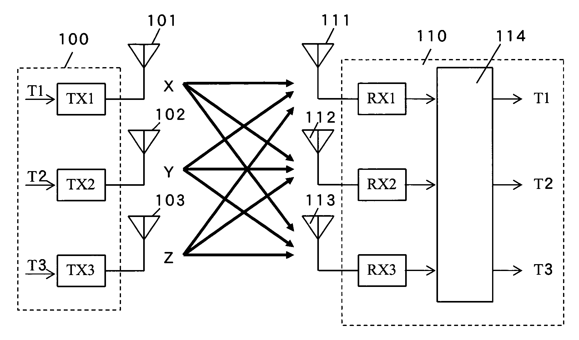
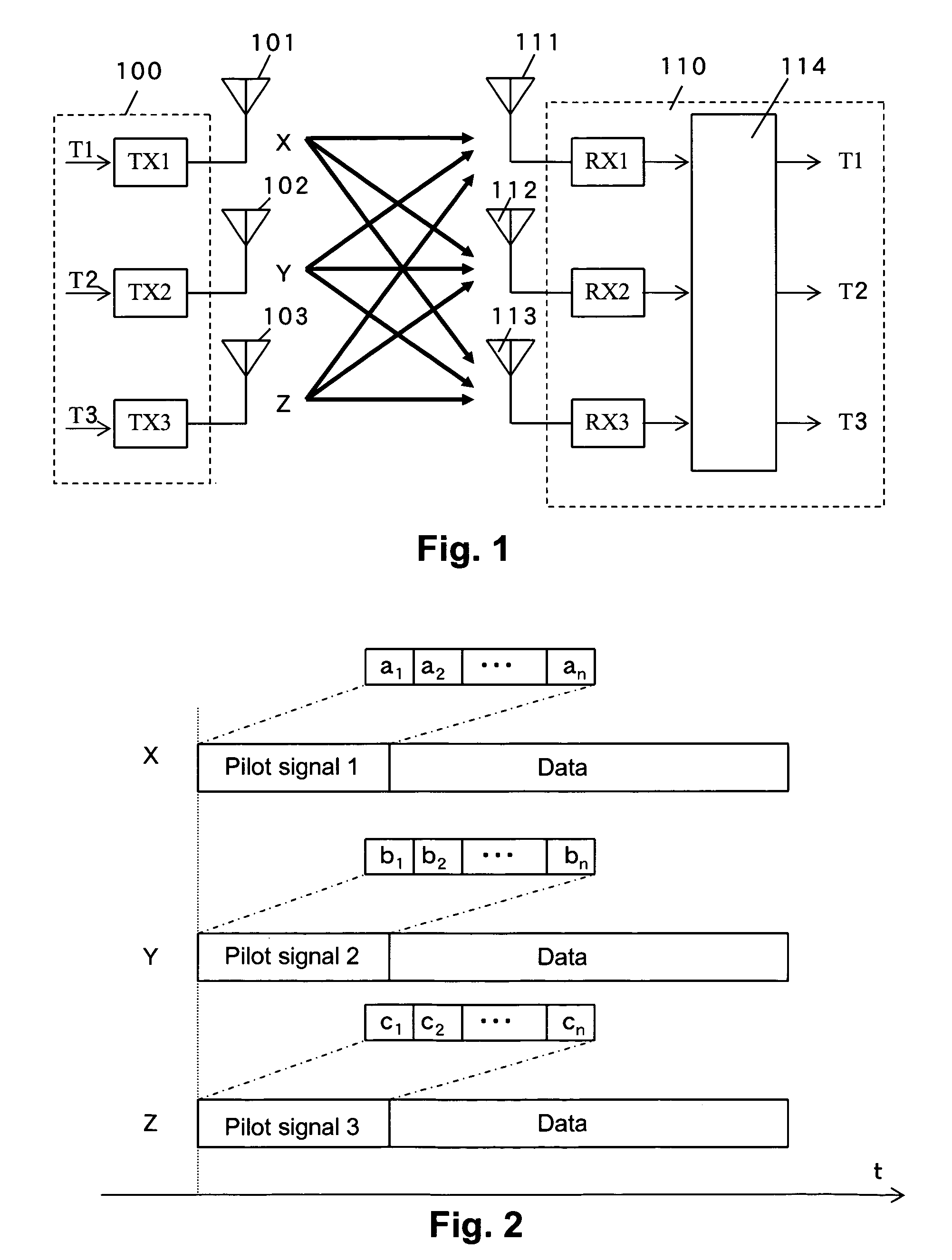
[0022]FIG. 2 shows a data structure of transmit signals sent from the respective antennas 101 through 103 shown in FIG. 1. Each of the transmit signals comprises a pilot signal and a data main body located behind the pilot signal. For convenience of explanation, only the pilot signals and the data main bodies are disclosed in the present embodiment. As shown in FIG. 2, the respective transmit signals are transmitted so as to overlap one another on a time base.

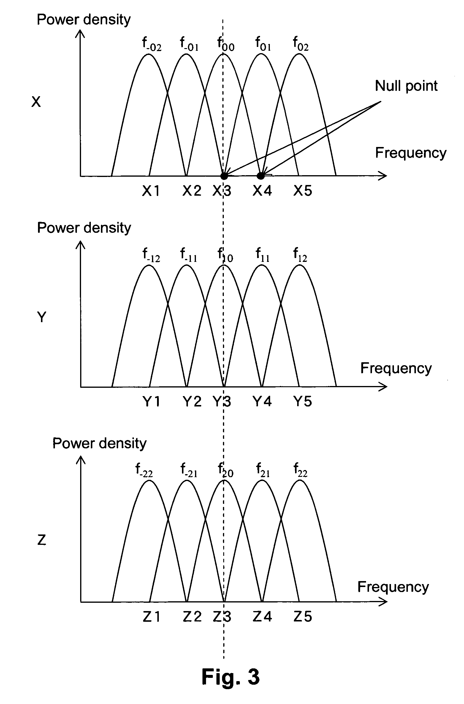
[0023]FIG. 3 shows transmit signals for describing the relationships among power densities thereof and frequencies thereof. In FIG. 3, fij (where i and j are arbitrary integers) indicate subcarriers. The adjacent subcarriers are set so as not to interfere with one another. In FIG. 3 as well, Xi, Yi and Zi (where i are arbitrary integers) respectively indicate data strings of pilot signals of respective subcarriers. For example, Xi=(x1, x2, . . . , xn)(where n: positive integer).

[0024]The feature of the present invention resides...

second preferred embodiment

[0043]Combinations of respective pilot signals of transmit signals transmitted from respective antennas, whose pilot signals are placed in an orthogonal relationship, will next be explained using FIG. 4.

[0044]A description will first be made of a case in which a transmitting device and a receiving device respectively make use of two antennas. In this case, let's assume that in FIG. 1, the transmitting device 100 carries out communications using the antennas 101 and 102 and the receiving device 110 performs communications using the antennas 111 and 112. As shown in FIG. 4(A), respective pilot signals of subcarriers of a transmit signal X meet a relationship of (X1, X2, X3, X4, X5)=(A, B, C, D, E). Here, A through E indicate orthogonal code strings or sequences different from one another. On the other hand, respective pilot signals of subcarriers of a transmit signal Y satisfies a relationship of (Y1, Y2, Y3, Y4, Y5)=(F, G, H, I, J). Here, F through J indicate orthogonal code sequence...


PUM


Abstract

With the objective of making it possible to accurately estimate a transmission line and accurately demodulate a signal by a receiving device, the present invention provides a transmission system suitable for use between a transmitting device that performs transmission using first and second transmitting antennas, and a receiving device that performs reception using a plurality of receiving antennas, wherein a pilot signal transmitted through the first transmitting antenna is made orthogonal to a pilot signal transmitted through the second transmitting antenna.

Description

BACKGROUND OF THE INVENTION[0001]1. Field of the Invention[0002]The present invention relates to an orthogonal frequency division multiplexing (hereinafter abbreviated as “OFDM”) signal transmission system, and particularly to a data structure of pilot signals employed in an MIMO (Multiple Input Multiple Output) system using a transmitting device equipped with a plurality of antennas and a receiving device equipped with a plurality of antennas, and an OFDM transmission system using the same.[0003]2. Description of the Related Art[0004]A patent document 1 (Japanese Unexamined Patent Publication No. 2004-96186) discloses a conventional data structure of pilot signals and an OFDM transmission system using the same. In the patent document 1, an intermittent pilot system has been disclosed in the OFDM signal transmission system. Here, the pilot signals are used to know or recognize transfer functions from antennas on the transmitting side to antennas on the receiving side.[0005]According...

Claims


Application Information

Patent Timeline
Patent Type & Authority Patents(United States)
IPC IPC(8): H04J11/00H04J99/00
CPCH04L5/0026H04L5/0048H04L25/0204H04L25/0226H04L27/2613H04B7/04
Inventor AKAHORI, HIROJI
Owner LAPIS SEMICON CO LTD
Why Eureka
Try Eureka