Two-stroke engine

a two-stroke engine and engine technology, applied in combustion engines, machines/engines, mechanical equipment, etc., can solve the problems of deteriorating exhaust gas values, inability to complete the filling of the transfer channel distant from (distal to) the exhaust,

Active Publication Date: 2008-04-29
ANDREAS STIHL AG & CO KG
View PDF15 Cites 19 Cited by
  • Summary
  • Abstract
  • Description
  • Claims
  • Application Information

AI Technical Summary

Benefits of technology

[0003]It is an object of the present invention to provide a two-stroke engine of the aforementioned kind that is of a simple configuration and has minimal exhaust gas values.

Problems solved by technology

At the same time, a complete filling with air of the transfer channels remote from (distal to) the exhaust is not achieved.
This can lead to a deterioration of the exhaust gas values.

Method used


Image

  • Two-stroke engine
  • Two-stroke engine
  • Two-stroke engine

Examples


Embodiment Construction

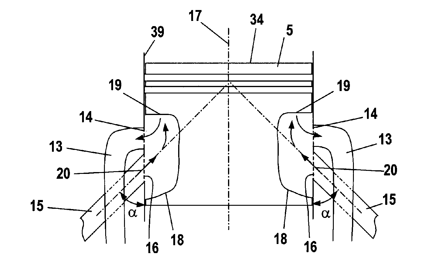
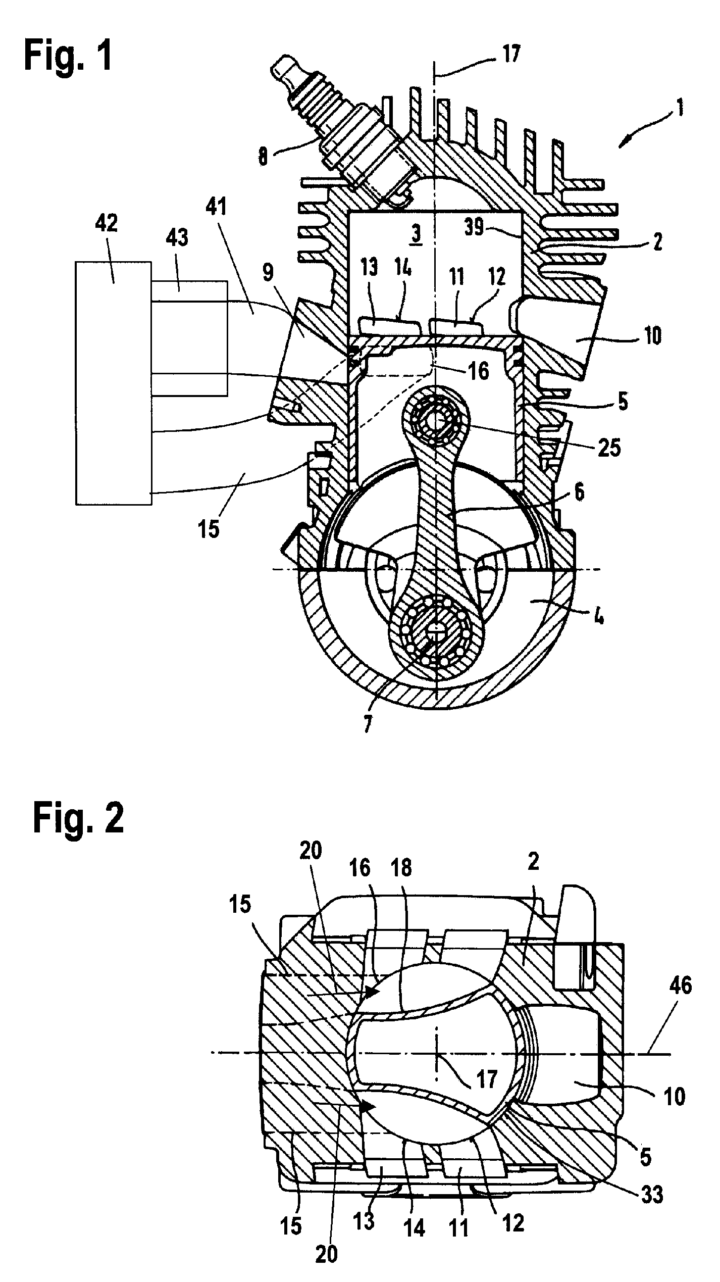
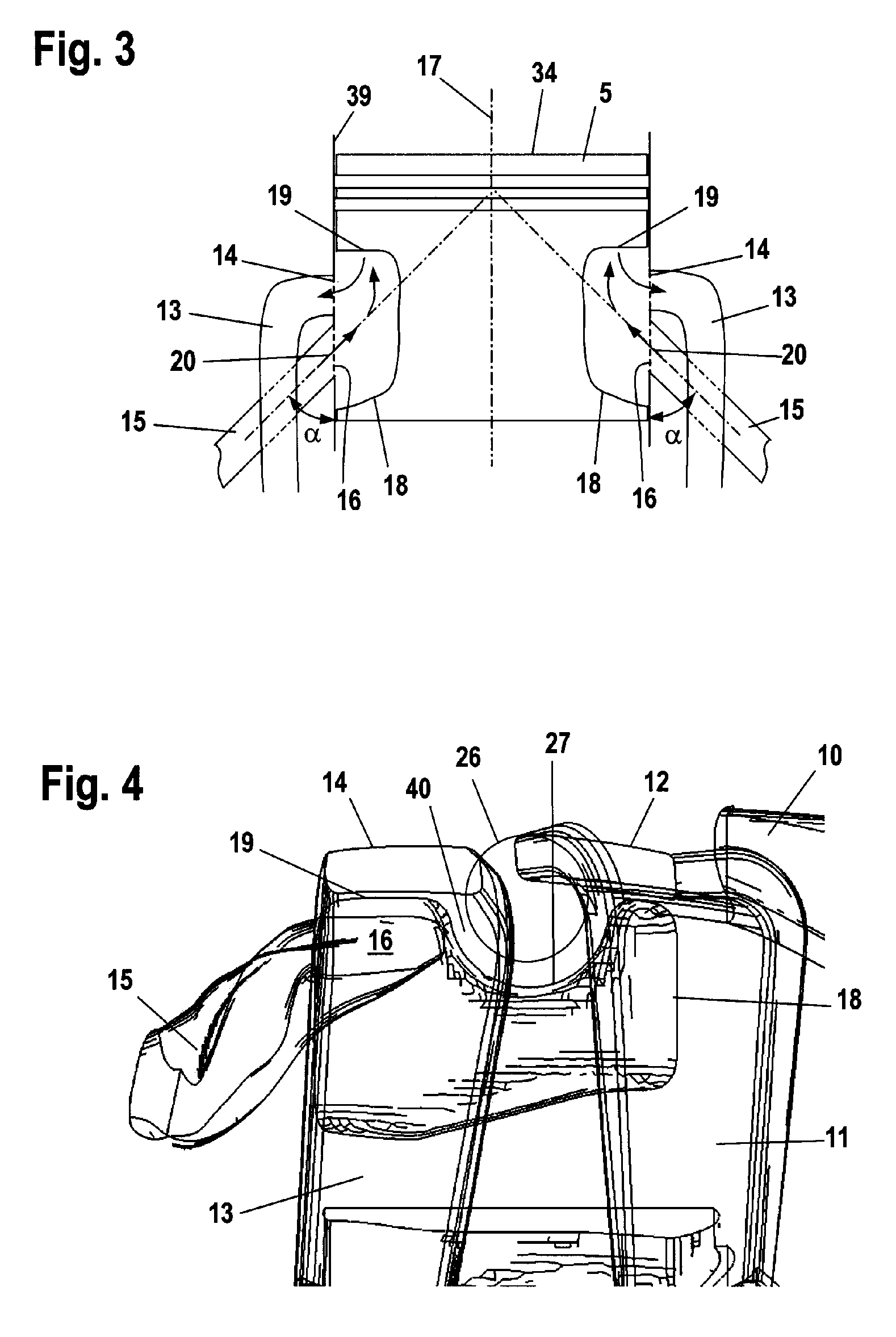
[0034]The two-stroke engine 1 illustrated in FIG. 1 comprises a cylinder 2 in which a combustion chamber 3 is formed. A spark plug 8 projects into the combustion chamber 3. The combustion chamber 3 is delimited by a piston 5 that reciprocates within the cylinder 2. The piston 5 drives by means of a connecting rod 6 the crankshaft 7 that is rotatably supported in a crankcase 4. The piston 5 is connected to the connecting rod 6 by means of a piston pin 25. The piston 5 moves within the cylinder 2 in the direction of the longitudinal axis 17 of the cylinder. The two-stroke engine 1 has an intake 9 through which a fuel / air mixture is supplied to the crankcase 4. The intake 9 is connected by a mixture channel 41 to an air filter 42 through which ambient air is sucked in. A section of the mixture channel 41 is formed within carburetor 43 in which fuel is supplied to the combustion air. An exhaust 10 extends away from the combustion chamber 3; exhaust gases can escape from the combustion c...


PUM


Abstract

A two-stroke engine has a cylinder and a piston reciprocating in the cylinder and delimiting a combustion chamber. The piston has at least one piston recess. A crankshaft is rotatably arranged in a crankcase connected to the cylinder. A connecting rod connects piston and crankshaft. Transfer channels connect the crankcase to the combustion chamber in pre-defined piston positions. The transfer channels each have a transfer port opening into the combustion chamber. A device for supplying fuel and an air channel supplying combustion air are provided. In predetermined piston positions, the air channel is connected by the piston recess to the transfer ports. The air channel opens into the cylinder bore opposite the exhaust for the exhaust gases. The air channel, the piston recess, and the transfer channels define an air passage that provides approximately uniform distribution of air from the air channel into the transfer channels.

Description

BACKGROUND OF THE INVENTION[0001]The invention relates to a two-stroke engine comprising a cylinder in which a combustion chamber is provided that is delimited by a reciprocating piston. The piston drives by means of a connecting rod the crankshaft rotatably supported in a crankcase. In pre-defined piston positions, the crankcase is connected to the combustion chamber by means of at least two transfer channels wherein each transfer channel opens with a transfer port into the combustion chamber. The engine comprises a device for supplying fuel and an air channel for supplying combustion air. In predetermined piston positions, the air channel is connected by a piston recess provided at the piston to the transfer ports of the two transfer channels. An exhaust for the exhaust gases generated in the combustion chamber is provided wherein the air channel opens into the cylinder bore on a side opposite the exhaust. The air channel, the piston recess, and the transfer channels define an air...

Claims


Application Information

Patent Timeline
Patent Type & Authority Patents(United States)
IPC IPC(8): F02B33/04F02B25/00
CPCF02B25/16F02B25/22
Inventor KLIMMEK, AXELKAMINSKI, SILKEGEYER, WERNERSCHMIDT, ROLANDROITSCH, TOMMYBLECHSMIDT, RALFBAHNER, ANDREASSCHMIDT, OLAF
Owner ANDREAS STIHL AG & CO KG
Why Eureka
Try Eureka