Traveling apparatus and method for controlling thereof

a technology of traveling apparatus and control device, which is applied in the direction of sport apparatus, electric devices, cycles, etc., can solve the problems of similar discrepancies between the target direction and the actual travel direction, and rider falling down by centrifugal for

Inactive Publication Date: 2008-04-29
TOYOTA JIDOSHA KK
View PDF6 Cites 107 Cited by
  • Summary
  • Abstract
  • Description
  • Claims
  • Application Information

AI Technical Summary

Benefits of technology

[0236]In the present invention when a turn is performed in accordance with a shift of the barycentric position to the right and left, the barycentric position coming close to a position of the wheel is detected to restrict rotational velocity of the wheel. As a result, an abrupt turn in which the rider may fall down by the centrifugal force is prevented from occurring and stable traveling can be obtained without fail.
[0237]Further in the present invention, the level difference of the road surface is predicted by the change of a signal from the acceleration sensor in the gravitational direction (Z-axis) of the vehicle to control the rotation of the wheel with respect to the state of falling from the level difference. As a result, when traveling on the road surface having a considerable level difference and the wheel going apart from the road surface to fall freely in the air, the rider can land safely.
[0238]According to an aspect of claim 1 of the present invention, a traveling apparatus includes: a means for driving a plurality of wheels independently and a chassis connecting the plurality of wheels, in which a means for detecting a barycentric shift of a rider is provided in the chassis to perform traveling by respectively setting rotational velocity of the plurality of wheels in accordance with information on the detected shift of the barycenter, wherein turning is performed in accordance with a shift of the barycentric position to the right and left and also a control means is provided for detecting that the barycentric position has come close to the position of the wheels and for restricting the rotational velocity of the plurality of wheels to a predetermined limited value, so that the occurrence of an abrupt turn in which the rider may fall down by the centrifugal force can be prevented and stable traveling can be obtained without fail.

Problems solved by technology

Moreover, when effective diameters of the wheels 3 become unequal due to a difference in gas pressure of the right and left wheels 3R and 3L, there is a possibility that the similar discrepancy arise between the target direction and the actual travel direction.
However, in a traveling apparatus such as the one mentioned above, there is a possibility that the rider falls down by the centrifugal force when a turn is suddenly made.
Due to the above, there is a problem that the rider falls down by the centrifugal force when the abrupt turn is made.
Moreover, when effective diameters of the wheels 3 become unequal due to a difference in gas pressure of the right and left wheels 3R and 3L, there is a possibility that the similar discrepancy arise between the target direction and the actual travel direction.
Due to the above, when traveling on a road surface having considerable level differences and when a wheel going apart from the road surface and then falls freely in the air, there occurs such a problem that the wheel is driven to a high speed rotation by the control unit.
When the wheel driven to such high speed rotation lands on the road surface, the vehicle abruptly runs; the posture becomes unstable; and then the rider cannot maintain the posture and falls down to result in a dangerous state, which is a problem.

Method used


Image

  • Traveling apparatus and method for controlling thereof
  • Traveling apparatus and method for controlling thereof
  • Traveling apparatus and method for controlling thereof

Examples


Embodiment Construction

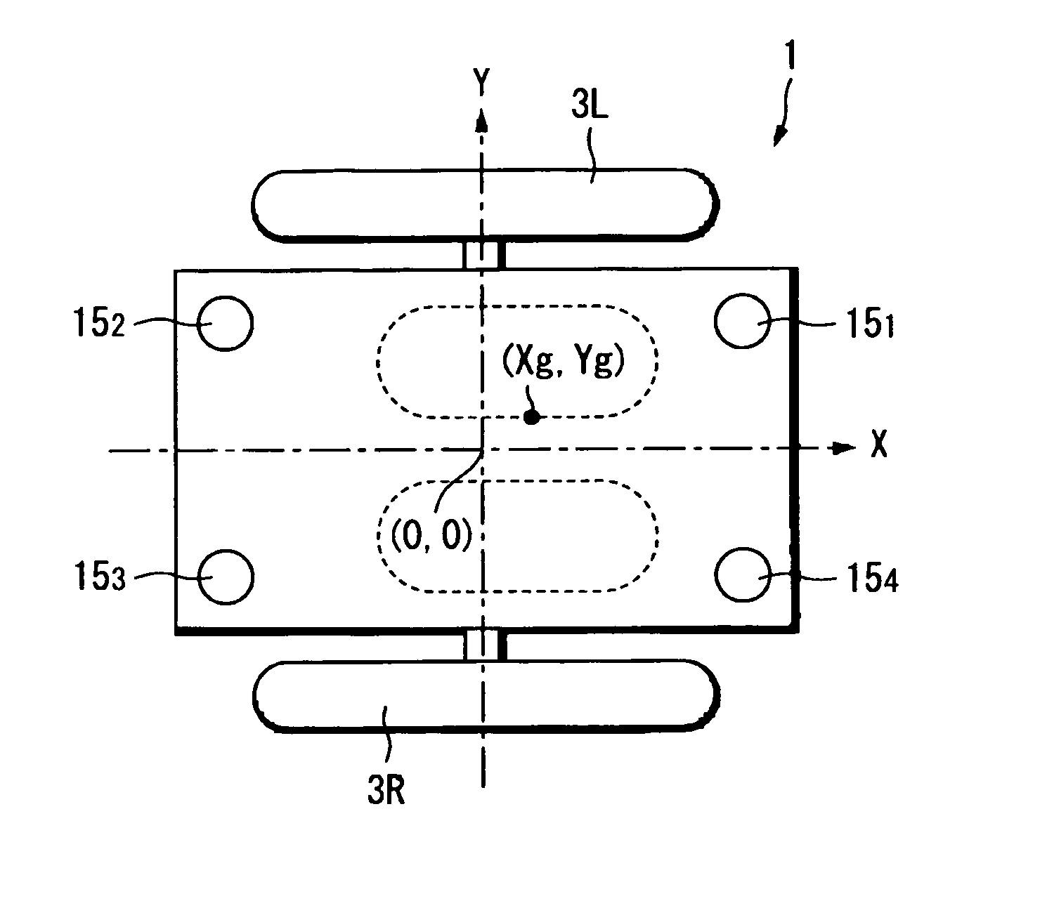
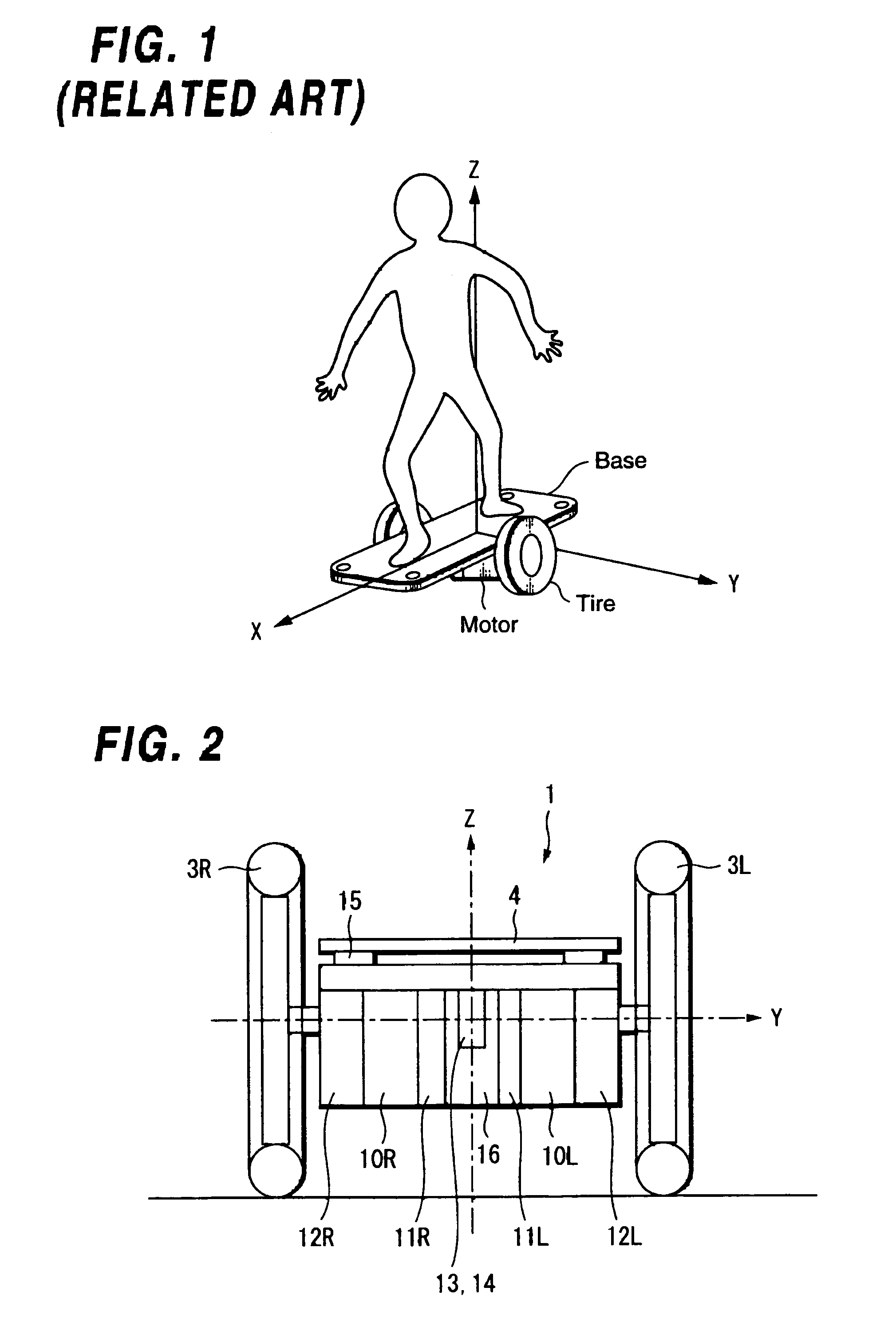
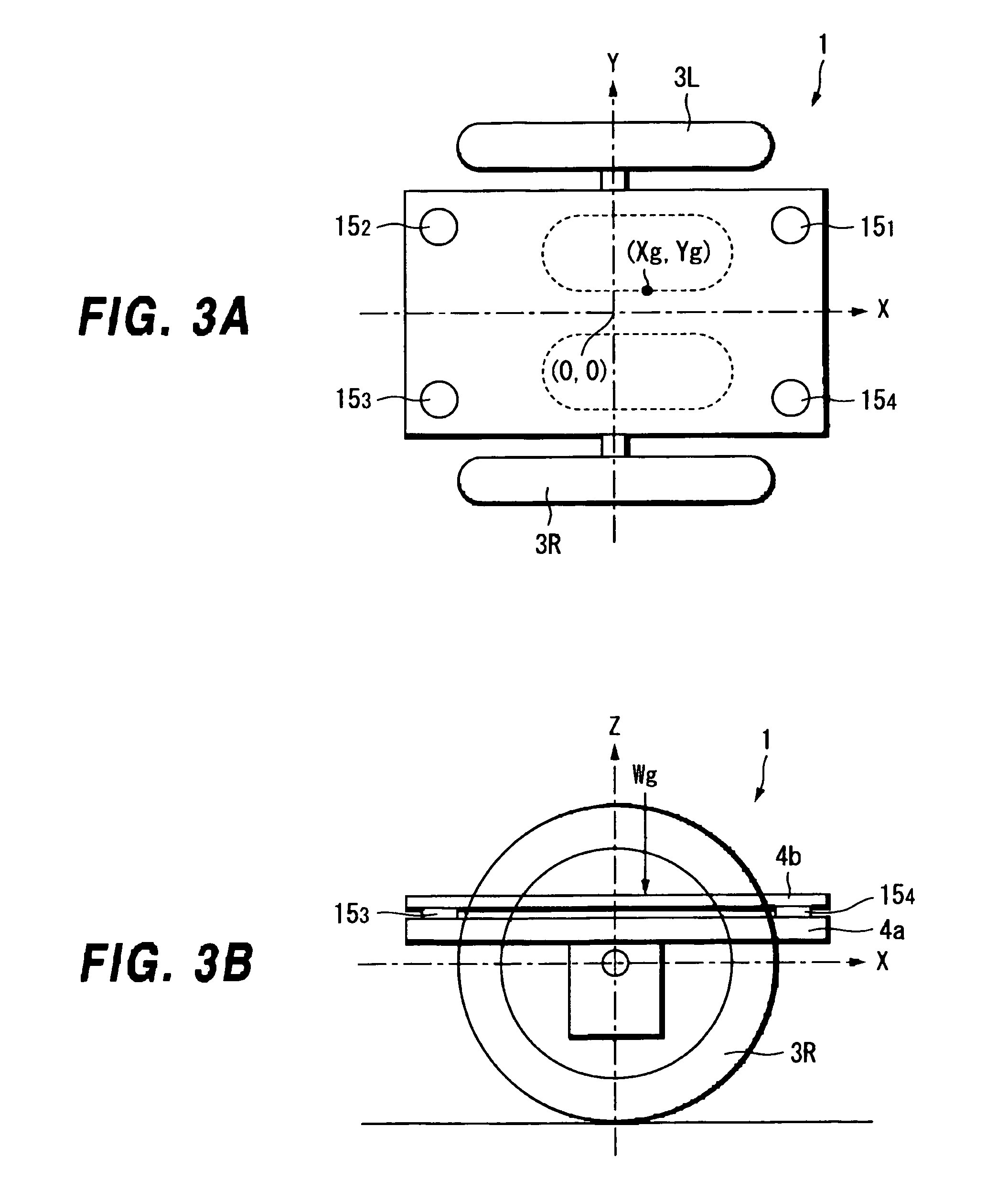
[0335]Hereinafter, an explanation is made to the present invention by referring to accompanied drawings. FIGS. 47A and 47B are diagrams showing a structure of an embodiment of a coaxial two-wheeled vehicle to which a traveling apparatus and a method for controlling thereof according to the present invention are applied, where FIG. 47A is a front view and FIG. 47B is a lateral view.

[0336]For example, right and left wheels 101 and 102 are provided in FIG. 47. Those two wheels 101 and 102 are arranged such that respective wheel axles 104 and 105 are disposed on a straight line of a table (chassis) 103. Further, right and left motors 106 and 107 are respectively disposed close to the wheels 101 and 102 on the table 103, and rotary shafts 108 and 109 of those right and left motors 106 and 107 are connected to the wheel axles 104 and 105 respectively through transmission portions (reducers) 110 and 111, so that the wheels 101 and 102 can be rotationally driven.

[0337]Further, a sensor circ...


PUM


Abstract

A traveling apparatus suitable for use in a two-wheeled traveling vehicle on which a man rides, and a method for controlling thereof, are provided. An abrupt turn, which can make a rider fall down, is prevented, and stable traveling is obtained without fail. Specifically, the apparatus and method efficiently charge regenerative energy that is generated when decelerating or traveling on a downward slope. The apparatus and method include motors for driving a plurality of wheels independently, a chassis for connecting the plurality of wheels, in which sensors for detecting a shift of barycenter of a rider are provided, and a controller for restricting a rotational velocity of each of the plurality of wheels to a predetermined limited value, wherein turning is performed in accordance with the shift of a barycentric position.

Description

BACKGROUND OF THE INVENTION[0001]1. Field of the Invention[0002]The present invention relates to a traveling apparatus suitable for use in, for example, a two-wheeled traveling vehicle on which a man rides and to a method for controlling thereof; specifically, relates to the apparatus and method in which charging with regenerative energy that is, for example, generated when decelerating or traveling a downward slope is efficiently performed to obtain excellent traveling.[0003]2. Description of the Related Art[0004]For example, a two-wheeled traveling vehicle on which a man rides has been proposed (for example, refer to a patent reference 1).[0005][Patent reference 1] U.S. Pat. No. 6,288,505Specification[0006]For example, the applicant of the present invention has previously proposed a traveling apparatus described hereunder (Japanese Patent Application No. 2003-168224) as a two-wheeled traveling vehicle on which a man rides.[0007]First, FIG. 1 is a perspective view showing an extern...

Claims


Application Information

Patent Timeline
Patent Type & Authority Patents(United States)
IPC IPC(8): B60K1/00B62D61/00A63C17/08A63C17/12B62D37/00
CPCA63C17/08A63C17/12B62D37/00B62D61/00B62K3/007B60L15/20B60L2200/16B60L2200/24B60L2220/46B60L2240/22B60L2240/423B60L2260/34B60L2270/145B62K11/007Y02T10/64Y02T10/72
Inventor ISHII, SHINJI
Owner TOYOTA JIDOSHA KK
Why Eureka
Try Eureka