Pulverizing apparatus and method for pulverizing

a technology of pulverizing apparatus and pulverizing method, which is applied in the direction of grain milling, solid separation, instruments, etc., can solve the problems of not disclosing the specifics of the rotor system or address, and achieve the effect of improving the pulverizing efficiency of the fluidized bed type pulverization/classification apparatus and improving the accuracy of obtaining particles

Active Publication Date: 2008-04-29
RICOH KK
View PDF5 Cites 12 Cited by
  • Summary
  • Abstract
  • Description
  • Claims
  • Application Information

AI Technical Summary

Benefits of technology

[0015]The present inventors have recognized that pulverizing efficiency of a fluidized bed type pulverization / classification apparatus can be improved by optimizing a shape or size of a rotor, which will also operate to improve the accuracy of obtaining particles of a desired size.
[0016]The above-mentioned background fluidized bed type pulverization / classification apparatuses can be improved by optimizing a shape or size of a rotor, which will also operate to improve the accuracy of obtaining particles of a desired size.
[0018]The present inventors recognized, for these reasons, that a need exists for a novel pulverizing apparatus that can process particles to be pulverized efficiently, improve efficiency of a collision in a milling chamber and a crush device, shorten the time to provide the crushing device, and crush particles to a desired size range with high efficiency.

Problems solved by technology

Both publications do not disclose specifics of a rotor system or address balance of centrifugal force and centripetal force of the rotor.

Method used


Image

  • Pulverizing apparatus and method for pulverizing
  • Pulverizing apparatus and method for pulverizing
  • Pulverizing apparatus and method for pulverizing

Examples


example 1

[0083]Preparation of Pulverizing Apparatus:

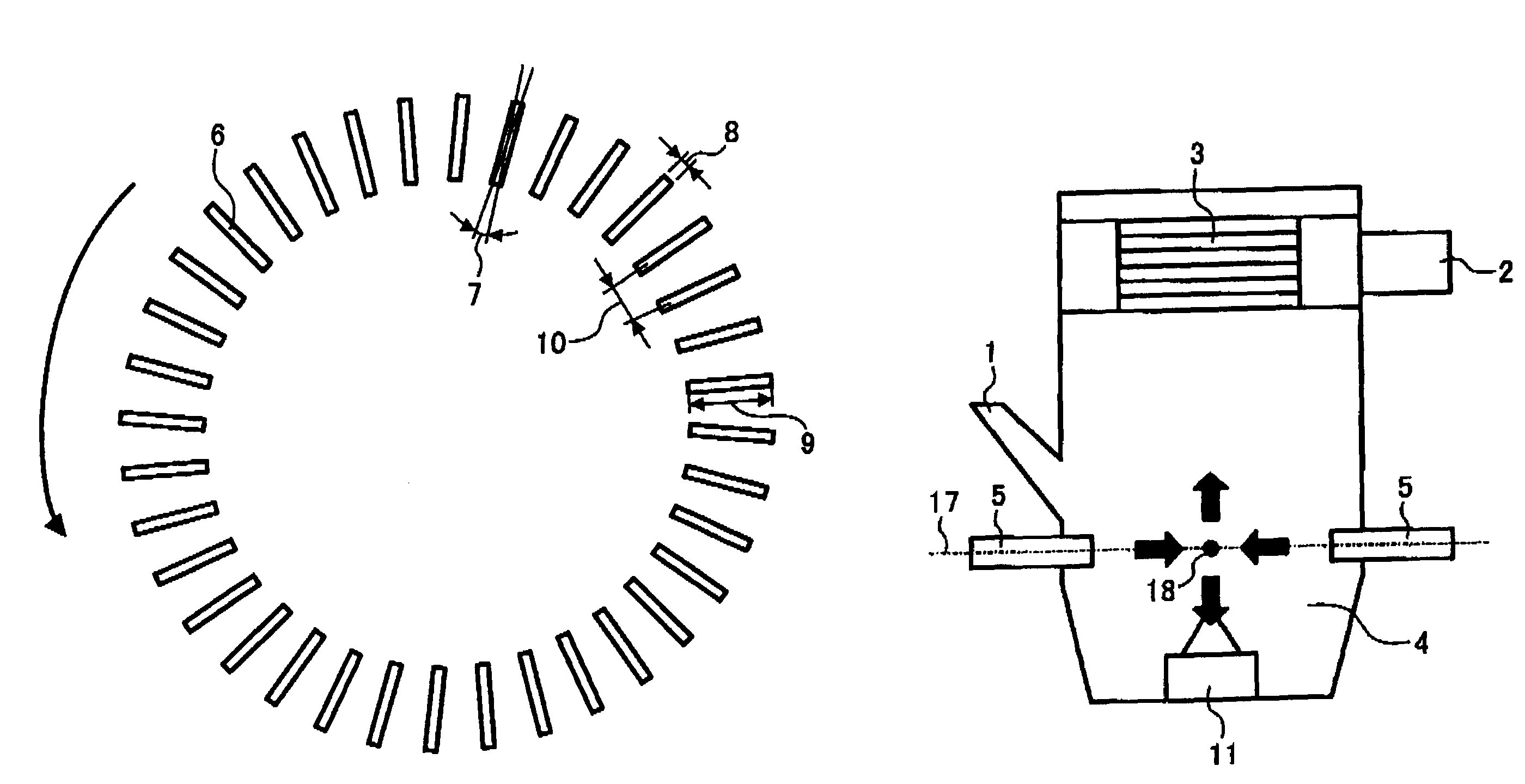
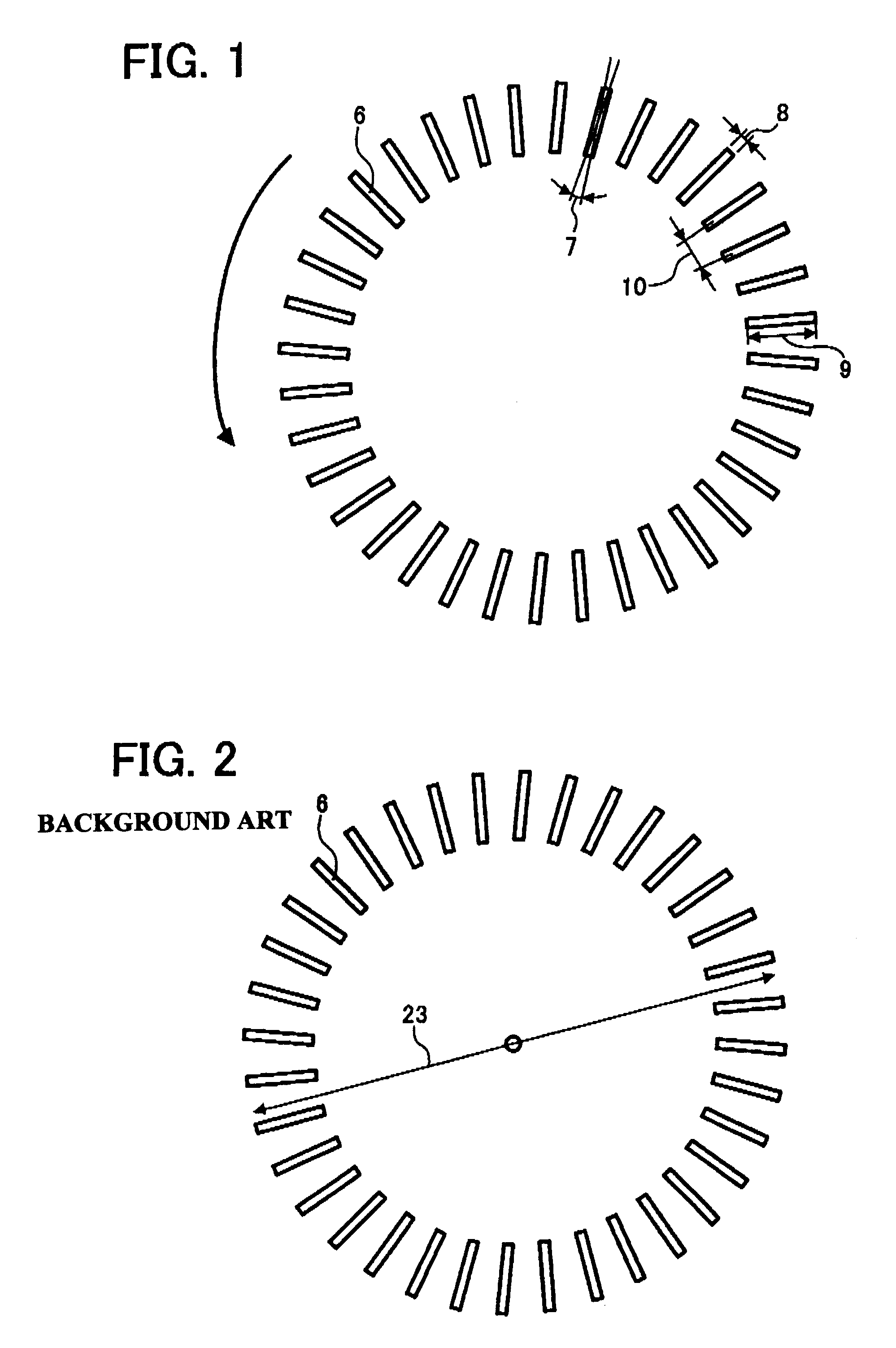
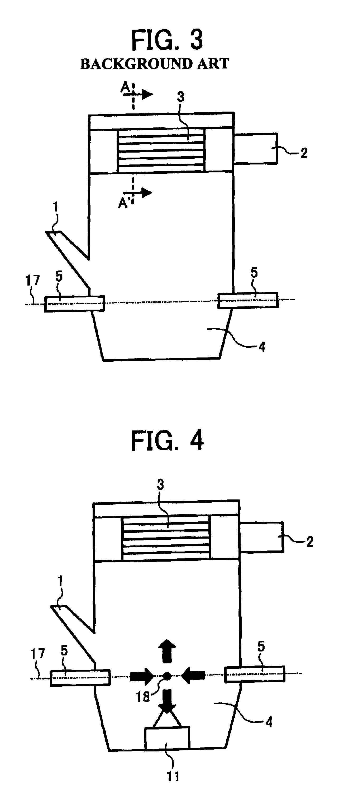
[0084]A pulverizing apparatus as shown in FIG. 3 and a rotor as shown in FIG. 1 with a rotor specification were prepared as follows.

[0085]Rotor:[0086]external diameter: 100 mm[0087]width of each blade of the rotor: 1 / 50 of rotor diameter=2 mm[0088]Length of each blade: 1 / 20 of rotor diameter=5 mm[0089]Angle of each blade: 0°[0090]Pagination of blades: 50

[0091]Number of rotors: 1

[0092]Internal diameter of Milling chamber: 250 mm

[0093]Height of pulverizing apparatus: approximately 900 mm

[0094]Air nozzle exit diameter: 6.5 mm

[0095]Number of air nozzles: 3

[0096]The air nozzles were placed at equal intervals (equiangular degree) along the wall of milling chamber 4. To be suitable for 0° from horizontal direction, the direction of the exit of air nozzles 5 was set.

[0097]With the above-mentioned crushing device in this example, air nozzles 5 were set at the position of the first collision such that point 18 (FIG. 4) became the center axis of most ...

example 2

[0111]The same device as in example 1 except also including a first secondary collision member 11.

[0112]The centerline of the air nozzles 5 set up below the first collision member 11 from the intersecting position (the position 18: compressed air first collides mutually attended with particles) right under 60 mm mutually as shown in FIG. 4.

[0113]Particles of the above-mentioned composition were supplied on the following conditions, and the particles were pulverized.

[0114]Original pressure of the compressed air supplied to air nozzles 5: 0.5 MPa

[0115]Rotation peripheral velocity of rotor 3: 30 m / s

[0116]Obtained fine particles were as follows.

[0117]Volume average particle size: 5.96 μm (MULTICIZER by Coulter Electronics)

[0118]Fine particles content rate of 4 μm or less (piece several %)

[0119]:65.6%

[0120]Rate of row particles content of 16 μm or more (weight %): 1.1%

[0121]Amount of pulverizing processing: 14.2 Kg / hr

example 3

[0122]The same device as in example 1 except including secondary collision member 12.

[0123]As shown in FIG. 5, the collision plate member 12 was installed at a position 60 mm above the centerline of the air nozzles 5 intersected mutually.

[0124]Particles of the above-mentioned composition were supplied on the following conditions, and the particles were pulverized.

[0125]Original pressure of the compressed air supplied to air nozzles 5: 0.5 MPa

[0126]Rotation peripheral velocity of rotor 3: 30 m / s

[0127]Obtained fine particles were as follows.

[0128]Volume average particle size: 5.88 μm (MULTICIZER by Coulter Electronics)

[0129]Fine particles content rate of 4 μm or less (piece several %): 66.5%

[0130]Rate of row particles content of 16 μm or more (weight %): 1.05%

[0131]Amount of pulverizing processing: 14.2 Kg / hr


PUM


Abstract

A pulverization / classification apparatus includes a plurality of air nozzles, a milling chamber as a space for pulverizing particles by compressed air jetted by the air nozzles, and a rotor installed at an upper part of the milling chamber that classifies powder materials flowing into the rotor from the milling chamber with centrifuging into fine particles and coarse particles. The rotor includes plural blade members, and a width of the blade members within the rotor are set to be 1 / 50- 2 / 25 of the rotor's diameter.

Description

BACKGROUND OF THE INVENTION[0001]1. Field of the Invention[0002]The present invention relates to a fluidized bed type pulverization / classification apparatus for manufacturing a powder, which may particularly be a toner powder, and a method of manufacturing the powder using the pulverization / classification apparatus.[0003]2. Discussion of the Background[0004]Background fluidized bed type pulverization / classification apparatuses typically have a cylindrical shape and include a vessel. In addition, plural air nozzles are provided on lower portions of an inner wall of the vessel to discharge a high pressure jetted air. In the cylindrical vessel, particles of a toner raw material (i.e., a toner constituent mixture) are suspended by the high pressure jetted air so as to collide with each other and thereby be pulverized. To efficiently perform pulverization while preventing excessive pulverization, the pulverized toner raw material needs to be rapidly fed to a classifier so that desired to...

Claims


Application Information

Patent Timeline
Patent Type & Authority Patents(United States)
IPC IPC(8): B02C19/06B02C23/08
CPCB02C19/065B02C19/066B02C23/10G03G9/0817
Inventor TANAKA, TETSUYAMAKINO, NOBUYASUSANTO, HIDEYUKI
Owner RICOH KK
Why Eureka
Try Eureka