
Method for regulating power for voice over Internet Protocol telephones

a technology of internet protocol telephones and power regulation, applied in the field of methods, can solve the problems of limited ip telephony, single point of failure, antiquated administration tools, etc., and achieve the effect of preventing poor service quality

Active Publication Date: 2008-04-29
CISCO TECH INC
View PDF25 Cites 94 Cited by
  • Summary
  • Abstract
  • Description
  • Claims
  • Application Information

AI Technical Summary

Benefits of technology

[0007]A particular embodiment provides the technical advantage of discriminating data based upon data type such that the voice VLAN may be given a higher priority than the native VLAN, thus increasing the quality of service for voice communications. Further, having telephony devices on separate VLANs becomes extremely useful when a large number of telephony devices are added to an existing network where the number of available IP addresses is not high enough to accommodate the large number of telephony devices. A separate voice VLAN, in accordance with the present invention, provides a new subnet and a new set of IP addresses.
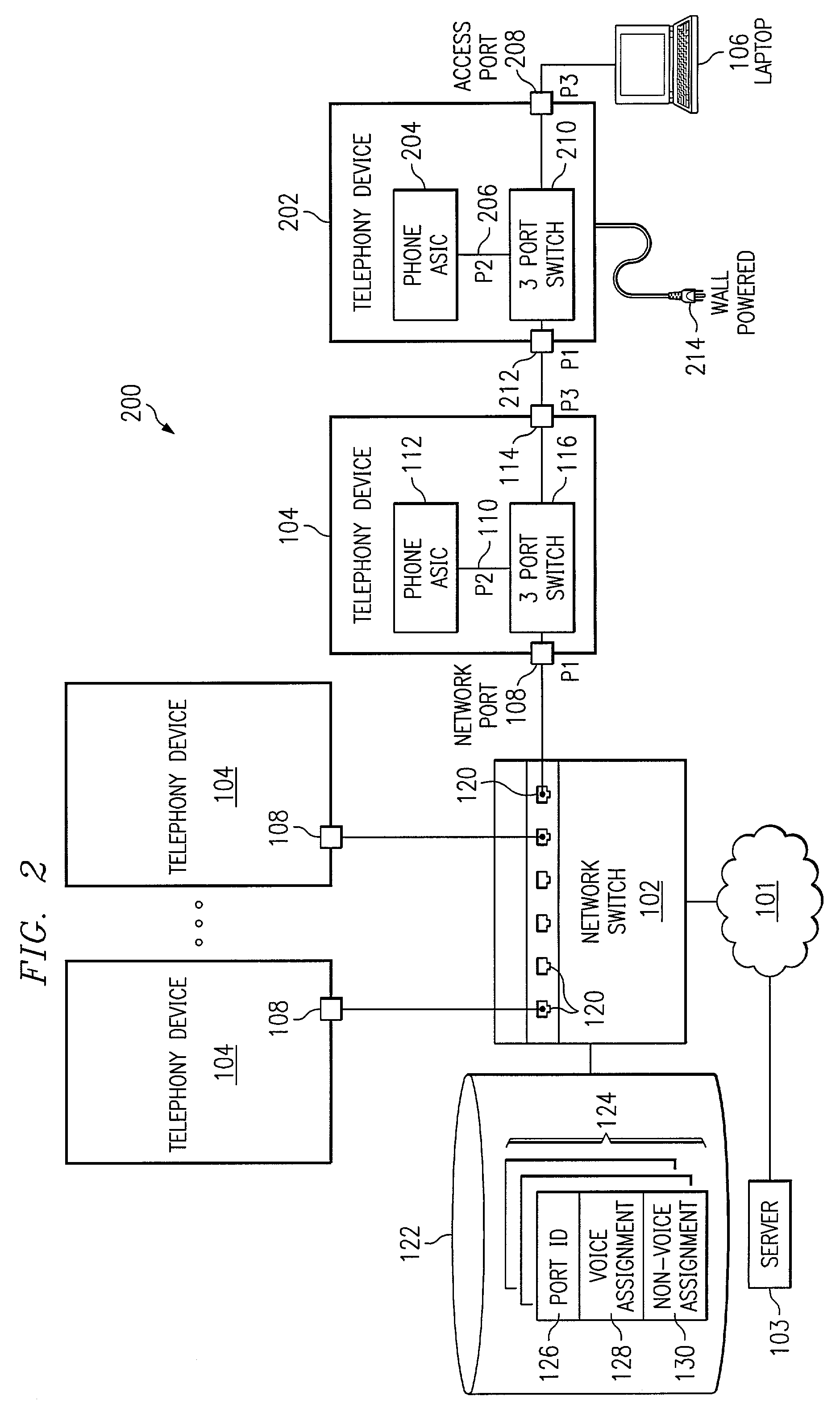
[0008]In accordance with another embodiment of the present invention, the network switch regulates and allocates power for a multi-VLAN port telephony device connected adjacent to the network switch, where the network switch is capable of providing power. This second embodiment provides the technical advantage of efficiently using available power at the network switch.
[0009]In accordance with still another embodiment of the present invention, the multi-VLAN port telephony device re-marks the header of incoming packets to designate the appropriate VLAN. This third embodiment provides the technical advantage of ensuring that non-voice data traffic is properly marked and not sent on the voice VLAN. In this way, a sending device may not circumvent the VLAN assignments provided by the network switch of the present invention.

Problems solved by technology

Despite the popularity of this conventional design, there are several problems with this kind of architecture.
The problems include a single point of failure, proprietary closed architecture, and antiquated administration tools.
Currently, IP telephony has limitations including poor quality of service.
Poor quality of service for IP telephony includes, but is not limited to, packet delays or collisions which cause anomalies in the voice transmission on the receiver's end, and disconnection of the sender from the receiver due to discontinuity in the data stream.
These problems can be attributed to the fact that the Internet is an unmanaged network of sub-networks with no resource allocation authority.
As a result, it is common to encounter situations where there are too many users trying to communicate too much data through an already saturated pipeline.
This problem is usually not present in corporate local or wide area networks since they generally have a resource allocation authority in the form of an engineer or manager.
However, if network traffic exceeds predicted levels in such a corporate local or wide area network, quality of service for IP telephony devices may also be poor.

Method used


Image

  • Method for regulating power for voice over Internet Protocol telephones
  • Method for regulating power for voice over Internet Protocol telephones
  • Method for regulating power for voice over Internet Protocol telephones

Examples


Embodiment Construction

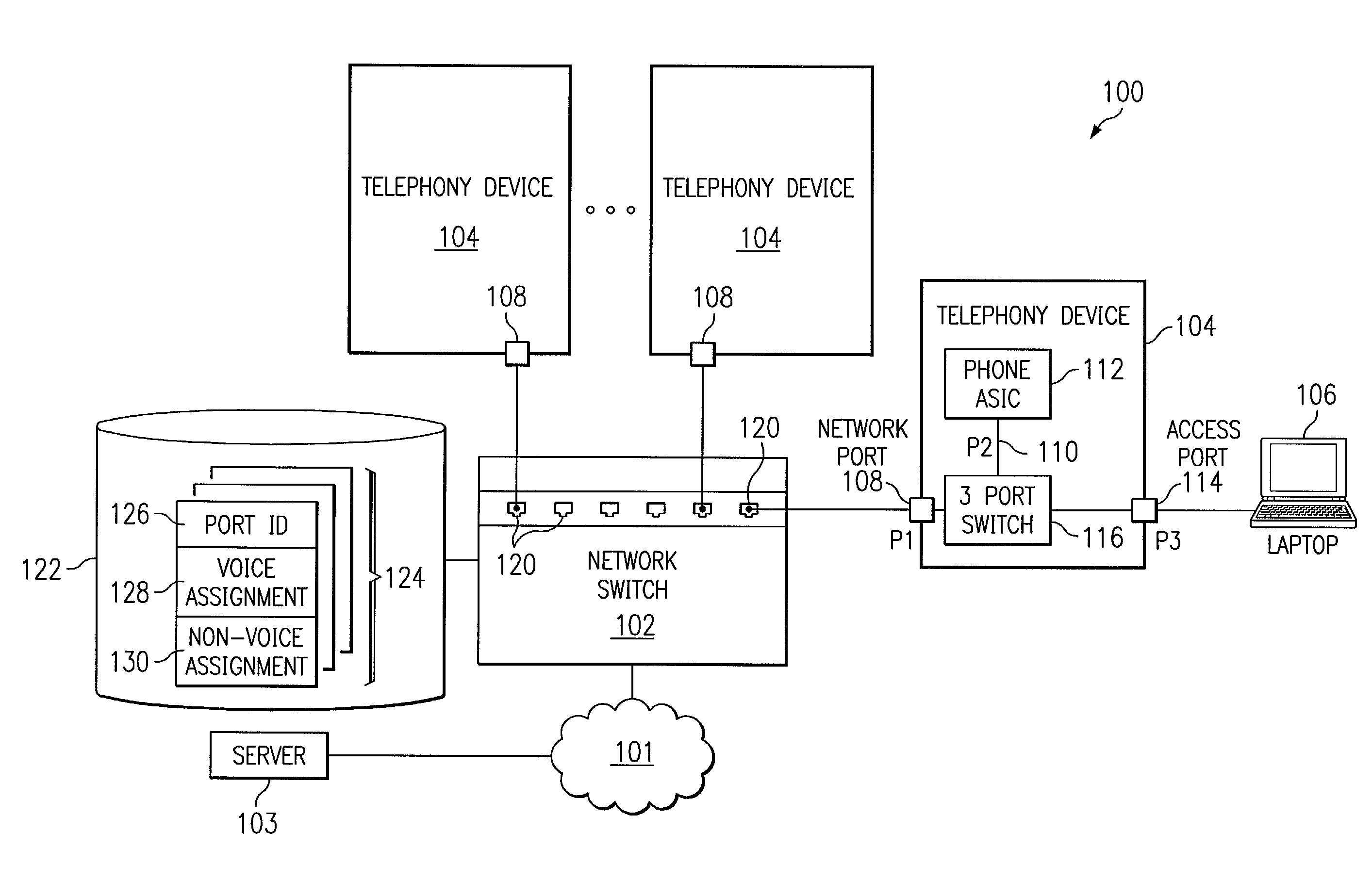
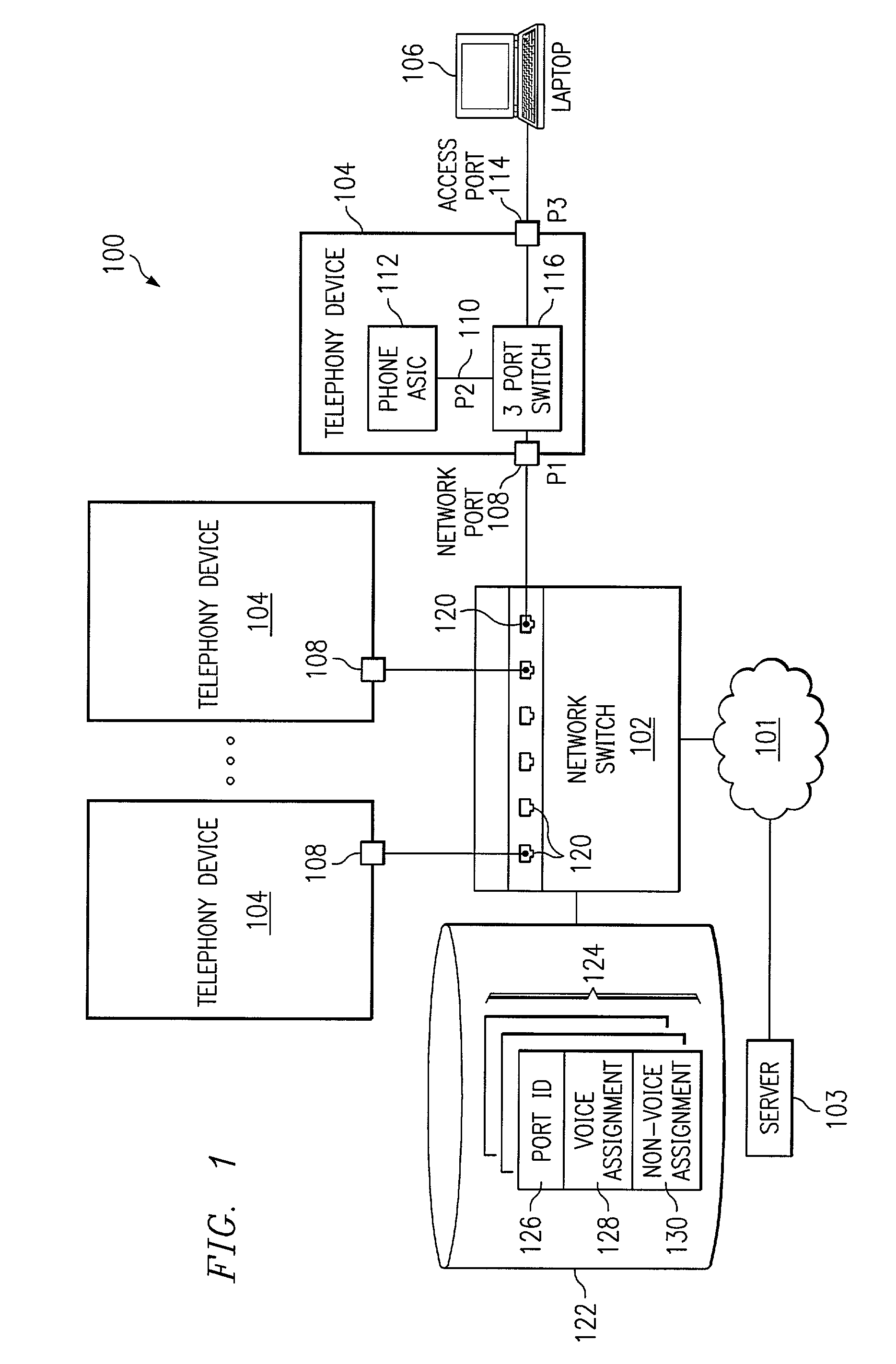
[0015]Now referring to the drawings, FIG. 1 illustrates telephony system 100 that includes a network 101, a network switch 102, connected to a multiple virtual local area network (“VLAN”) port telephony device (“telephony device”) 104 and an external network device 106. The external network device 106 may be a general purpose computer, computer server, or any other device which sends or receives data over a distributed network. A laptop is illustrated in FIG. 1, representative of any external network device 106.

[0016]Network 101 represents any hardware and / or software configured to communicate information in the form of packets, cells, frames, segments, or other portions of data (generally referred to as “packets”). Network 101 may include routers, hubs, switches, gateways, or any other suitable components in any suitable form or arrangement. Network 101 may include a server 103. Server 103 may assign network addresses to components of network 101. For example, server 103 may be a d...


PUM


Abstract

A system and method for implementing telephony devices in a distributed network environment is disclosed. The present invention provides for a network switch which provides power to a telephony device adjacently connected thereto.

Description

RELATED APPLICATIONS[0001]This application claims the benefit of U.S. Patent Provisional Application Ser. No. 60 / 285,507 filed Apr. 19, 2001, which is herein incorporated by reference for all purposes.TECHNICAL FIELD OF THE INVENTION[0002]The present invention relates generally to communication devices in a distributed network environment. In particular, the present invention relates to a system and method for implementing telephony devices in a distributed network environment, where a network switch supplies power to a telephony device adjacently connected to it.BACKGROUND OF THE INVENTION[0003]Nearly all business telephone systems are based on a centralized or star network design. In such a conventional system, all telephones and trunk lines converge on a single switching point, typically, a public branch exchange (“PBX”) or in some cases a programmable switch. Despite the popularity of this conventional design, there are several problems with this kind of architecture. The proble...

Claims


Application Information

Patent Timeline
Patent Type & Authority Patents(United States)
IPC IPC(8): H04L12/66
CPCH04L12/66
Inventor HABIB, AHSANARGANY, PERE JOAN MONCLUSTOUTIREDDY, KIRAN K.MCCLOGHRIE, KEITH
Owner CISCO TECH INC
Learn More