Vehicle drive assist system

a technology for assist systems and vehicles, applied in wave based measurement systems, process and machine control, navigation instruments, etc., can solve the problems of limited visibility in the backward area of the vehicle, driver's care is not high, and the limit in perfectly grasping the environmental conditions is not easy to achieve. , to achieve the effect of simple voice system and simple image display

Inactive Publication Date: 2008-04-29
FUJITSU GENERAL LTD
View PDF57 Cites 153 Cited by
  • Summary
  • Abstract
  • Description
  • Claims
  • Application Information

AI Technical Summary

Benefits of technology

[0024]Accordingly, an object of the present invention to provide a vehicle parking assist device which assists the driver in his driving, using a simple image display or simple voice system.

Problems solved by technology

When the grasping effort depends on only the sense, there is a limit in perfectly grasping the environmental conditions.
However, it is effective only in a direction in which the driver looks.
Further, visibility is limited in the backward area of the vehicle, so that the driver takes much care when he backs the vehicle into a narrow space.
Particularly, the parking technique is one of the most difficult driving techniques when a normal driver drives a vehicle.
IN the technique to park the vehicle, particularly, particular the technique to park the vehicle in a parking space between the adjacent vehicles of those being parked in a row in a back-to-front fashion (this parking will be referred to as a “series parking”) is one of the most difficult driving techniques when a normal driver drives the vehicle.
Further, since the driver backs the vehicle, a parking space in which the vehicle is to be parked is the dead space when viewed from the driver and the driver insufficiently knows the environment around the parking space.
Therefore, the technique fails to completely remove an anxiety of the driver.
The technique to merely display 3-dimensional images equidistantly arrayed along the traveling path predicted on the basis of a steering angle or move them along the traveling path is almost ineffective in checking a possibility that the vehicle will touch an obstructive object located near the predictive traveling path, because the driver must judge whether or not a steering angle of the steering wheel is proper.
For this reason, when the driver watches the display containing the backward area and the predictive traveling path curve, and judges if the predictive traveling path is proper, it is difficult for the driver to exactly judge if the predictive traveling path is proper.
Where the technique, as disclosed in JP-A-7-44799, to merely make an exact measurement of the parking space is used, it enables the drive to check if the parking space is sufficiently large, but it can unsatisfactorily assist the driver in the driving operation, which is necessary for the advancing of the vehicle to the parking space.
However, those related techniques do not always provide proper drive guide information having a simple construction.

Method used


Image

  • Vehicle drive assist system
  • Vehicle drive assist system
  • Vehicle drive assist system

Examples


first embodiment

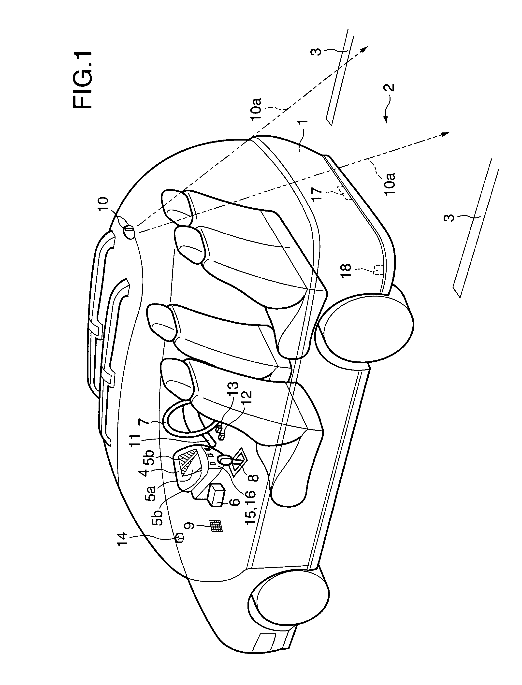
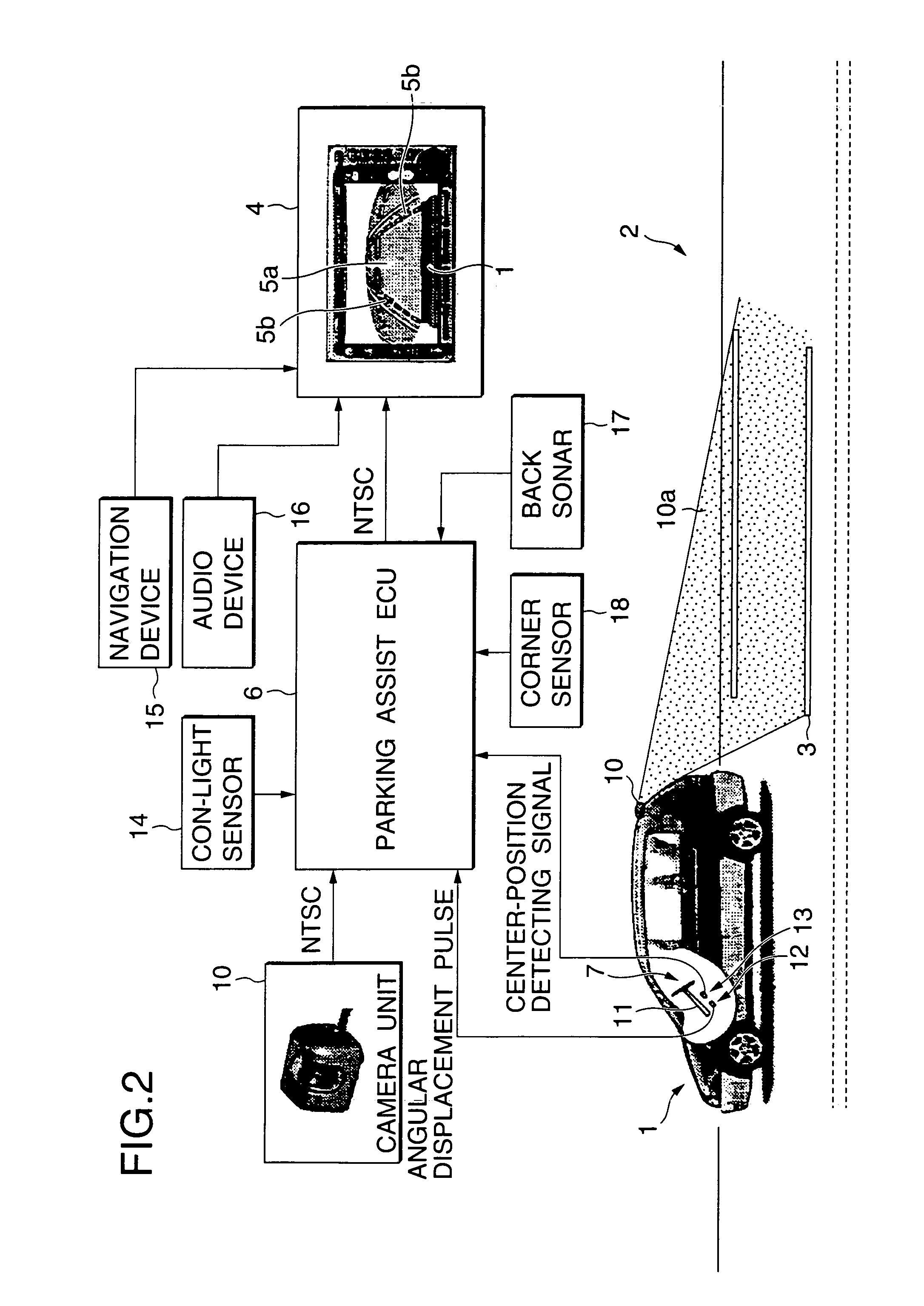
[0358]FIGS. 1 and 2 are diagrams showing a scheme of a vehicle parking assist device which is the present invention. Like reference numerals are used, for simplicity, for designating like or equivalent portions through the drawings which will be referred to in the description of the preferred embodiments of the invention.

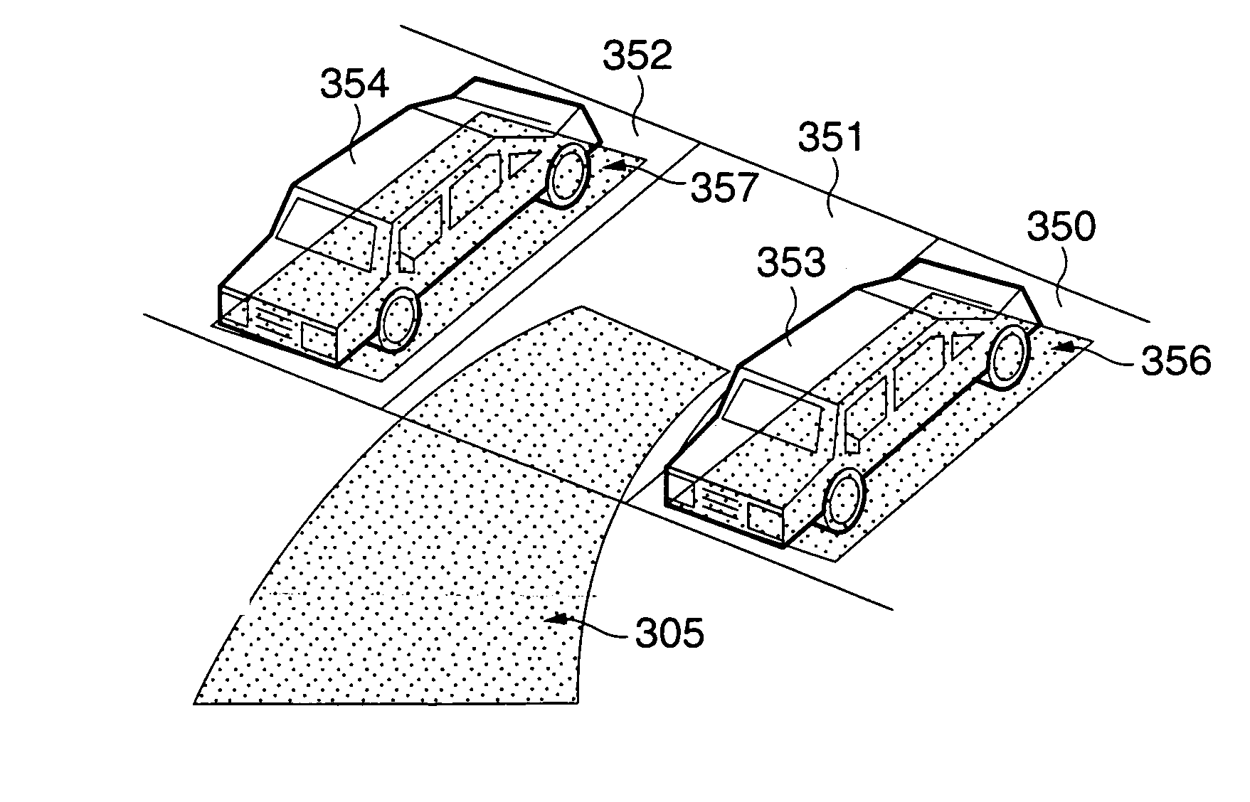
[0359]The vehicle parking assist device of the embodiment assists the driver to correctly park a vehicle into a parking space marked off with white lines 3 or the like, through the backward movement of the vehicle. A drive assist displays a predictive traveling path curve 5a representing as a predictive traveling path on the screen of an information display device 4 as display means, or white lines 5b prolonged from the lines demarcating both sides of a vehicle 1 on the display screen, whereby a drive assist for the driver is performed.

The predictive traveling path curve 5a and the white lines 5b are generated by an electronic control unit (referred to as a “parking...

third embodiment

[0387]FIG. 10 shows a scheme of a vehicle parking assist device which is the invention. In the embodiment, a plan model 60 is provided to select a series parking mode for a series parking assist 61 or a normal parking mode for a normal parking assist 62 on the screen of the information display device 4. In the normal parking mode, the field 50a of the camera unit 50 and the illumination by the back light 52 are directed mainly to the backward area of the vehicle 1. In the series parking mode, the field 50a of the camera unit 50 and the illumination by the back light 52 are directed to the side of the vehicle.

[0388]The series parking mode or the normal parking mode may be automatically selected. The series parking mode may be selected when the turning on of the winker lamp 63 or the hazard lamp 64 and the shifting of the shift lever 8 to the reverse gear position are simultaneously performed. In an alternative, the driver refers to map data about the present position of the vehicle 1...

fourth embodiment

[0389]FIG. 11 is a diagram showing the invention. In the embodiment, a plurality of camera units 10 are arranged around the body of a vehicle 1. Images output from those camera units 10 are simultaneously displayed on the same screen of the information display device. As shown, the camera units 10 are located at the front left L, the front right R and the back B of the vehicle 1. Each camera unit picks up a scene within the field 10a thereof.

[0390]Each of FIGS. 12(1) to 12(12) exemplarily shows segmented display areas formed by segmenting the screen of the information display device 4. The images output from the plurality of the camera units 10 are simultaneously displayed in those display areas, respectively. Where those areas are used, all the images may be watched on one screen. In the example of FIG. 12(1), the screen is segmented in a time divisional manner, and only the image of the backward area is displayed. The screen is automatically changed at fixed time intervals to disp...


PUM


Abstract

A vehicle drive assist system comprises a camera for picking up an image of an area existing in an advancing direction of a vehicle; display means for displaying the image picked up by the camera; steering angle detecting means for detecting a steering angle for steering the vehicle; traveling path predicting means for predicting a traveling path of the vehicle on the basis of the steering angle detected by the steering angle detecting means; and drive assist means for overlaying on the display means drive assist information containing the vehicle predictive traveling path predicted by the traveling path predicting means and guide lines prolonged from the lines defining the width of the vehicle body on the image of the area existing in the vehicle advancing direction.

Description

BACKGROUND OF THE INVENTION[0001]1. Field of the Invention[0002]The present invention relates to a vehicle parking assist device for assisting a driver in his driving by use of an image obtained by taking a scene of an area around a vehicle.[0003]2. Description of the Related Art[0004]To drive a vehicle, e.g., automobile, in safety, the driver needs to look traffic conditions around the vehicle attentively. The driver constantly watches the environment of the vehicle and makes efforts to grasp environmental conditions of the vehicle, while driving the vehicle. When the grasping effort depends on only the sense, there is a limit in perfectly grasping the environmental conditions. The human visual sensation is very important in grasping the environmental conditions. However, it is effective only in a direction in which the driver looks. The driver must drive the vehicle under the condition that areas that are shaded by the vehicle and from driver's view, i.e., the dead spaces, inevita...

Claims


Application Information

Patent Timeline
Patent Type & Authority Patents(United States)
IPC IPC(8): B64C13/18G01C22/00B60K35/00B60Q1/00B60Q1/48B60R1/00B60W30/06B62D15/02G01C21/36G05D1/02
CPCB60K35/00B60Q1/0023B60Q1/484B60Q9/005B60Q9/007B60R1/00B62D15/0275B62D15/028G01C21/005G01C21/3602G05D1/0246G05D1/0255B60K2350/1004B60K2350/106B60K2350/1084B60K2350/2013B60R2300/102B60R2300/103B60R2300/105B60R2300/106B60R2300/207B60R2300/301B60R2300/302B60R2300/303B60R2300/305B60R2300/306B60R2300/607B60R2300/70B60R2300/8053B60R2300/806B60R2300/8086B60T2201/10B60T2210/32B60W30/06G05D1/0272G05D2201/0213Y02T10/84B60W2050/146B60K2370/11B60K2370/152B60K2370/179B60K2370/21
Inventor SHIMIZU, TOSHIHIROSAKIYAMA, KAZUHIROSAKO, KAZUYA
Owner FUJITSU GENERAL LTD
Why Eureka
Try Eureka