Block

a technology of blocks and blocks, applied in the field of blocks, can solve the problems of reduced air tightness, labor-intensive fitting of blocks, and difficult assembly work of structures, and achieve the effects of easy assembling of structures, high air tightness, and enhanced working efficiency

Inactive Publication Date: 2008-05-06
HOKUSEI SHOJI
View PDF15 Cites 19 Cited by
  • Summary
  • Abstract
  • Description
  • Claims
  • Application Information

AI Technical Summary

Benefits of technology

[0004]The present invention has been made to solve the problems described above, and a main object thereof is to provide blocks which can be easily assembled into a highly airtight structure.
[0006]In this block, the left and right lower side faces and left and right upper side faces of the base body part are formed as the respective sloping faces. Further, the lower surface, upper surface and left side surface of the first protruding part protruding leftward from the base body part and the lower surface, upper surface and right side surface of a second protruding part protruding rightward from the base body part are each formed by a plurality of sloping faces. Furthermore, the faces of the lower portion of the block are each formed with a fitting groove, while the faces of the upper portion of the block are each formed with a fitting protrusion. As a result, the block can be fitted to other blocks without causing friction between the associated faces and simply by its own weight or by pushing in the block with a slight force. This makes it possible to easily assemble a structure which ensures high airtightness at the fitted portions of blocks.
[0007]Further, it is preferred that a right-hand half body and a left-hand half body are formed in rotationally symmetrical relationship with respect to the central vertical axis. With this construction, it is possible to dispense with work for distinguishing between the front and the back of a block in assembling a structure, thereby enhancing working efficiency.
[0008]Further, it is preferred that a branch part having a same shape as a shape of a right-hand or left-hand half body of the block is formed in a manner protruding from at least one of front and back surfaces of the block. With this construction, one structure can have another structure easily connected thereto.
[0009]Furthermore, an insertion hole through which a bar-like reinforcing member can be inserted is formed vertically through the block. With this construction, the reinforcing members are erected on a foundation for assembling a structure, for example, and each of the reinforcing members is inserted through the associated insertion hole, whereby the blocks are arranged in a side-by-side fashion. Thus, a structure which ensures high airtightness and rigidity can be easily assembled.

Problems solved by technology

Therefore, labor is required for fitting the blocks, which makes assembly work of the structure tough.
However, this method suffers from the problem that airtightness can be reduced to allow infiltration of rain water and the like.

Method used


Image

  • Block
  • Block
  • Block

Examples


Embodiment Construction

[0020]Hereinafter, the best mode of a block according to the present invention will be described with reference to the accompanying drawings.

[0021]First, the construction of a building block 1 (an example of a block according to the present invention) will be described with reference to the drawings.

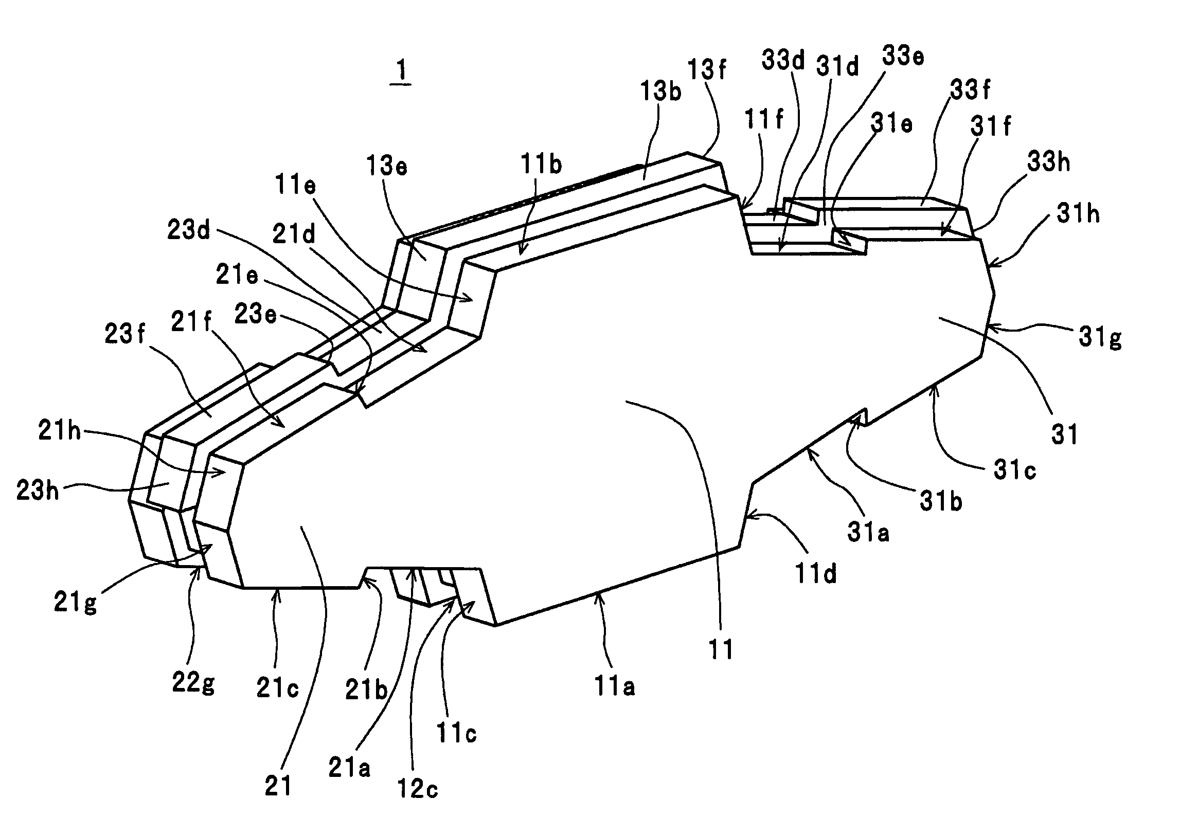
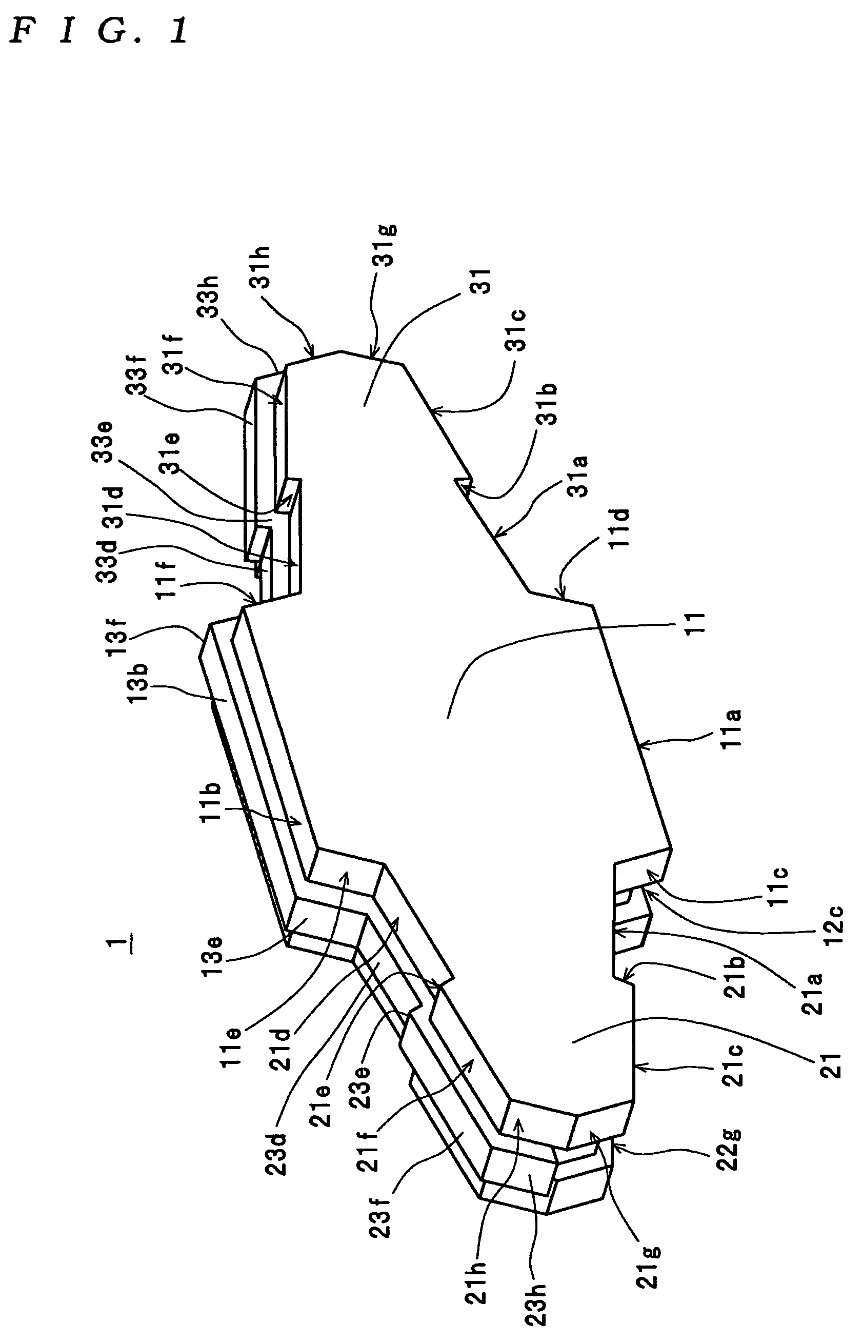
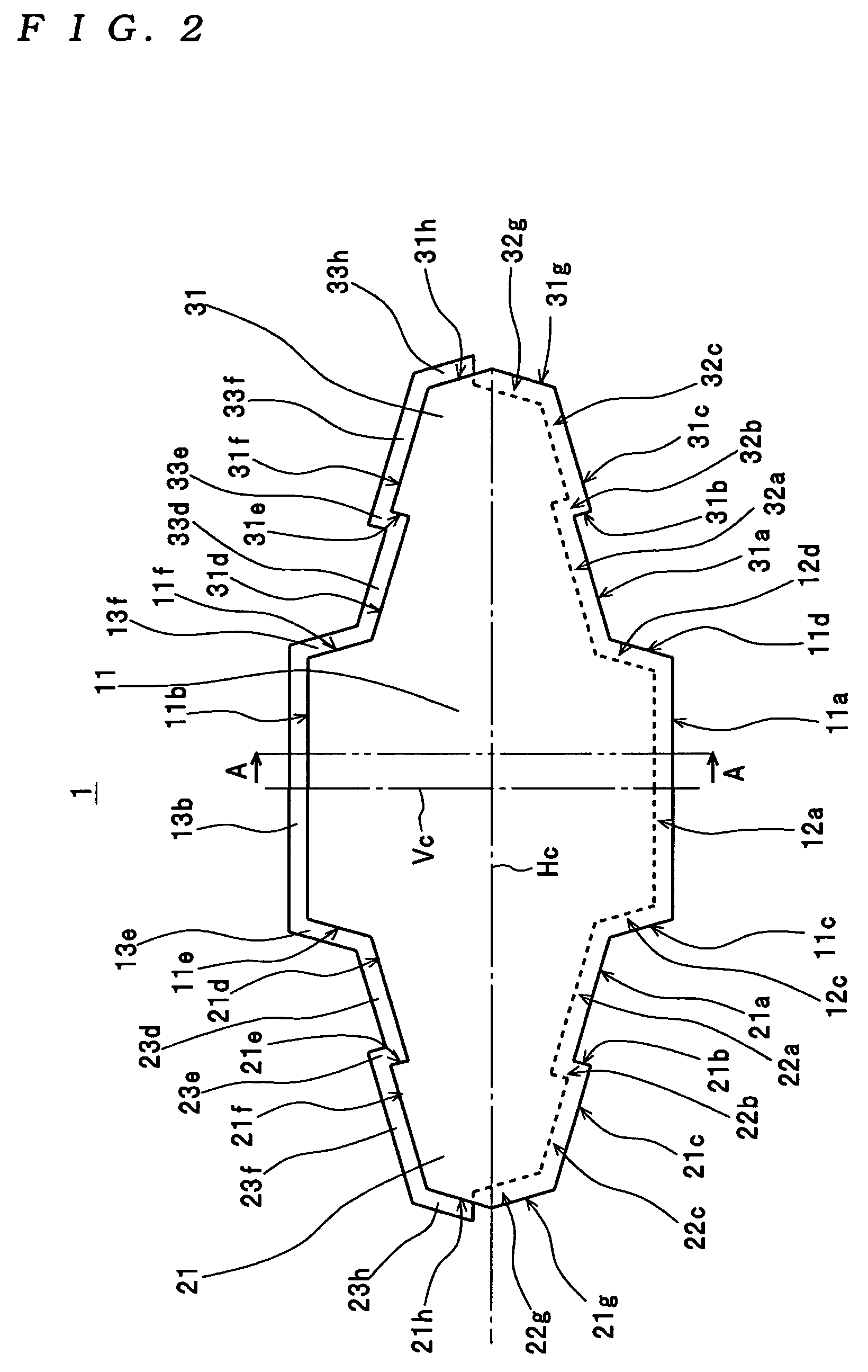
[0022]The building blocks 1 enable a wall-like structure to be assembled by arranging the same in a side-by-side fashion with parts thereof fitted to each other. For example, the building block 1 has reinforcing steel rods embedded therein, and is generally formed of concrete such that it has a plate shape with a predetermined thickness. In this case, as shown in FIG. 1, the building block 1 is integrally formed by a base body part 11 and protruding parts 21 and 31 protruding leftward and rightward, respectively, from the base body part 11 such that the building block 1 is generally cross-shaped in front view. Further, the building block 1 is formed such that the right-hand half body the...


PUM


Abstract

A block according to the present invention is a block comprising a base body part, a first protruding part, and a second protruding part, which are integrally formed with each other. The base body part has a left lower side face, a right lower side face, a left upper side face, and a right upper side face formed as respective sloping faces. The first protruding part has a lower surface thereof formed by first to third left-hand sloping faces, an upper surface thereof formed by fourth to sixth left-hand sloping faces, and a left side surface thereof formed by seventh and eighth left-hand sloping faces. The second protruding part has a lower surface thereof formed by first to third right-hand sloping faces, an upper surface thereof formed by fourth to sixth right-hand sloping faces, and a right side surface thereof formed by seventh and eighth right-hand sloping faces. The faces of the lower portion of the block are each formed with a fitting groove, and the faces of the upper portion of the block are each formed with a fitting protrusion.

Description

TECHNICAL FIELD[0001]The present invention relates to blocks that enable a structure to be assembled by arranging the blocks in a side-by-side fashion with parts thereof fitted to each other.BACKGROUND ART[0002]As a block of this kind, a block (1) is disclosed in WO00 / 43606. In this case, the block is formed with engaging parts (2, 2), a fitting protrusion (3), a fitting groove (4), and an insertion hole (5), and a plurality of blocks (1) can be stacked one upon another to thereby assemble a wall (structure) of a house or the like. To assemble these blocks (1) into a structure, while connecting laterally adjacent blocks (1) by fitting the engaging parts thereof to each other, each of the blocks (1) is stacked on another block positioned immediately below by fitting the fitting groove thereof on the fitting protrusion of the block positioned immediately below. This method makes it possible to assemble a highly airtight structure which is capable of preventing infiltration of rain wat...

Claims


Application Information

Patent Timeline
Patent Type & Authority Patents(United States)
IPC IPC(8): E02D29/02E04B2/02E04B2/08E04B2/12
CPCE04B2/08E04B2/12E04B2002/0206E04B2002/0254E04B2/04E04C1/00E04B2002/0204E04B2002/0232E04B2002/0226E04B2002/0267
Inventor TAKAYANAGI, HIROSHI
Owner HOKUSEI SHOJI
Why Eureka
Try Eureka