Railway hopper car discharge gate

a technology for hopper cars and discharge gates, which is applied to railway components, tipping wagons, wagons/vans, etc., can solve problems such as product contamination, difficulty in discharge, and reduced outward flow of lading, so as to avoid damage to gate panels and other components, enhance vacuum sealing, and improve efficiency

Active Publication Date: 2008-05-06
AERO TRANSPORTATION PRODS
View PDF39 Cites 83 Cited by
  • Summary
  • Abstract
  • Description
  • Claims
  • Application Information

AI Technical Summary

Benefits of technology

[0008]Various aspects of the hopper car discharge gate of the present invention include improved sealing and glide systems that provide for unimpeded flow of lading during discharge, a simplified method of assembly using multiple stacked frames that may be independently fabricated, a low-wear glide system that avoids damage to gate panels and other components due to friction, and an improved sealing system that protects lading from contaminants such as rain, dust and insect infestation and provides enhanced vacuum sealing for greater efficiency during vacuum discharge.
[0009]In one embodiment of the discharge gate a generally horizontally disposed gate panel is provided that is movable in opposite directions between an open position and a closed position. A frame structure defines a discharge opening for flow of material from the hopper car, and has first and second spaced side members presenting first and second edges respectively at the discharge opening extending generally in the directions of movement of the panel. Flexible seal strips on the side members extend along the respective edges and project into the discharge opening. Transversely spaced support surfaces for the panel are provided which underlie the seal strips. The panel is mounted on the support surfaces for movement between its opened and closed positions in sliding contact with the seal strips to thereby seal the discharge opening when the panel is closed and, when opened, provide for discharge of material through the opening without accumulation at the edges of the side members and the support surfaces.

Problems solved by technology

In the case of fine materials such as sugar, flour or cement, difficulties may be encountered during discharge due to significant quantities of the material becoming airborne.
Such difficulties can lead to product contamination.
In addition, fine materials may tend to accumulate on or within the elements of the discharge gate causing reduced outward flow of the lading, clogging of the discharge opening, and / or malfunction of the gate.
Attachment of a boot, however, is slow and awkward and the area of the gate where the boot attaches may not be sanitary.
Difficulties in the prior art devices, however, persist relative to the seals formed between elements within the gate assembly, particularly between outer hopper or frame elements and sliding panels.
In addition, surfaces for supporting the panels are prone to fouling due to build-up of transported matter, and wear due to friction caused by repetitive sliding of the panels over the support surfaces.

Method used


Image

  • Railway hopper car discharge gate
  • Railway hopper car discharge gate
  • Railway hopper car discharge gate

Examples


Embodiment Construction

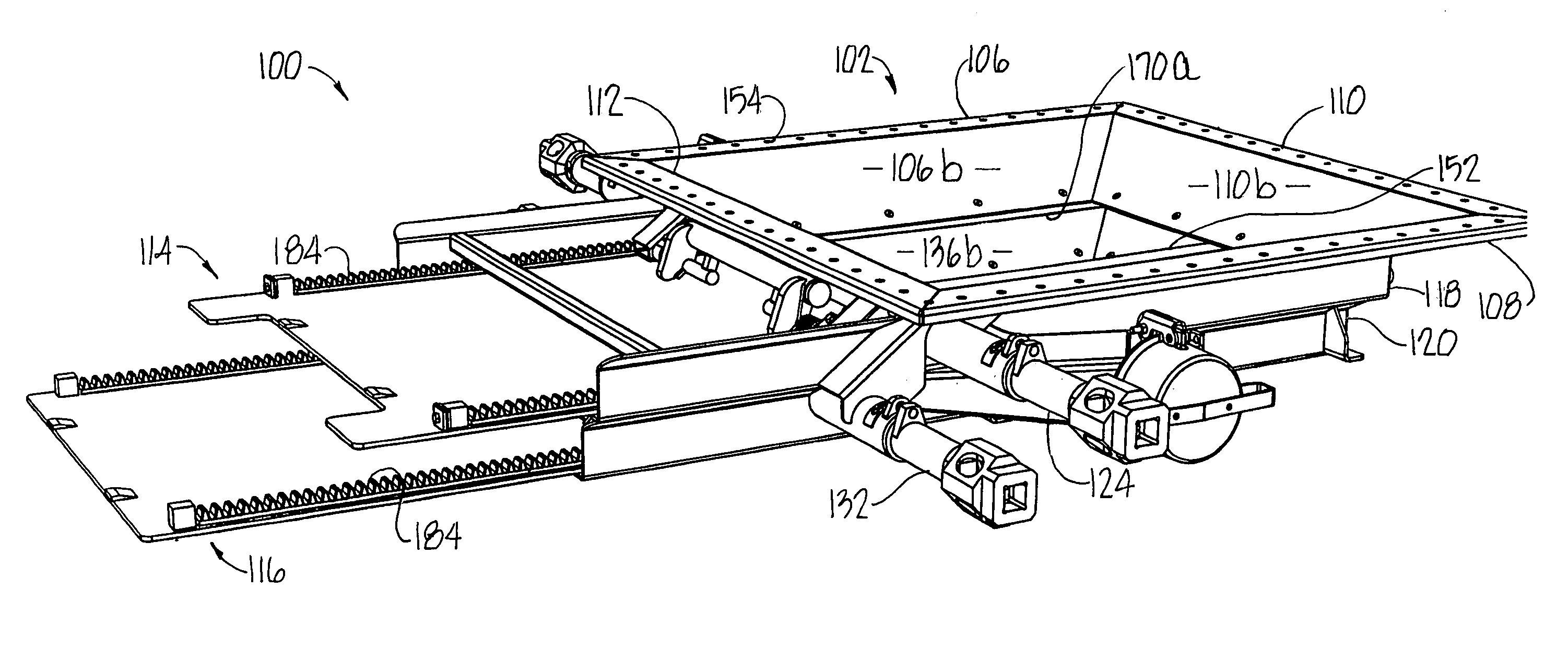
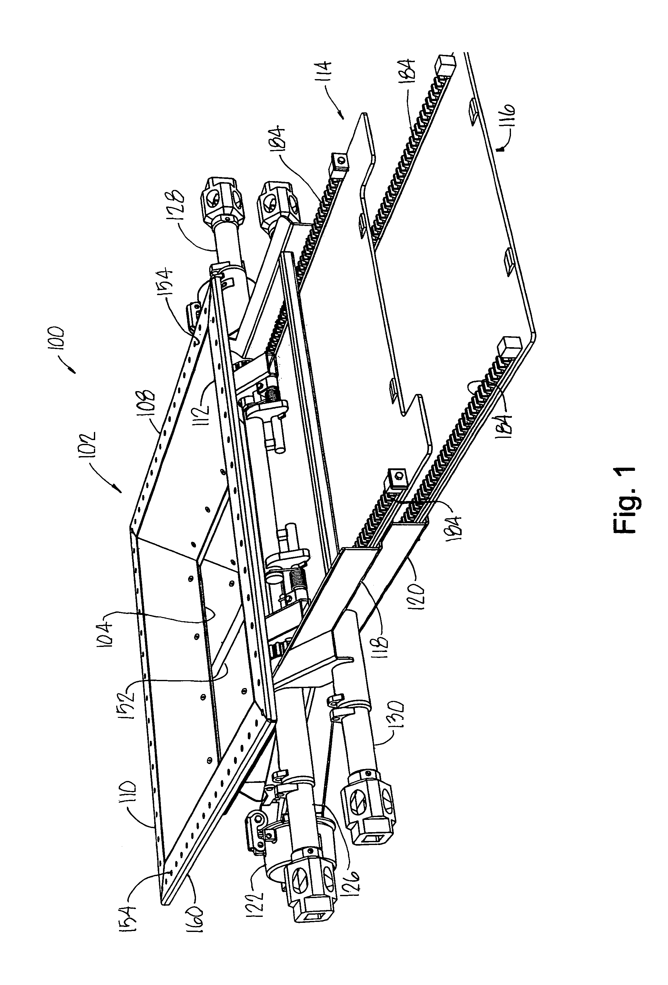
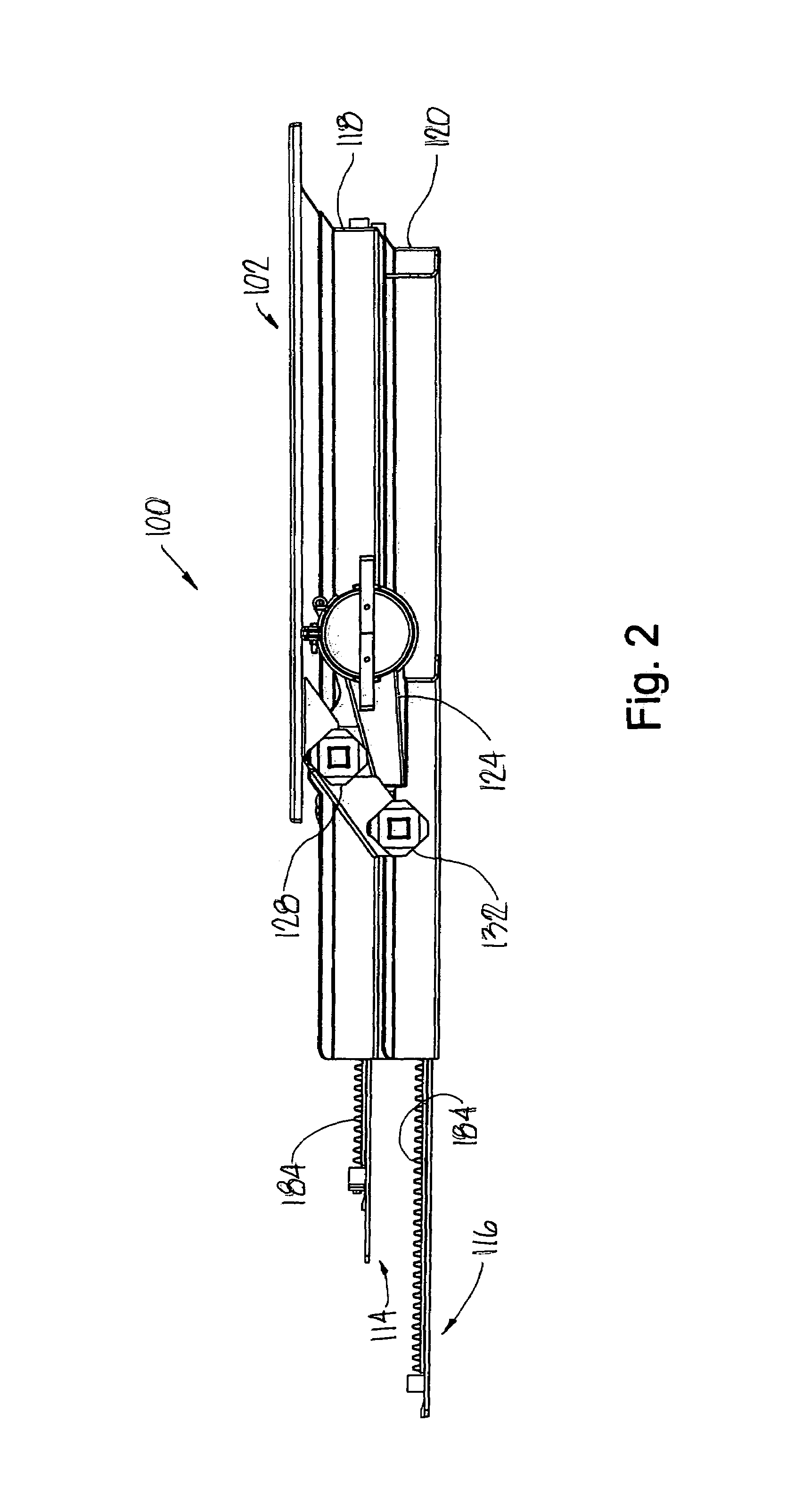
[0032]Referring now to the drawings, and initially in particular to FIGS. 1-8, wherein like reference numerals indicate like parts throughout the several views, a railroad hopper car discharge gate 100 is illustrated and includes a generally rectangular upper frame or hopper 102 surrounding a generally rectangular discharge opening 104 (see FIG. 6). The upper frame 102 includes four upper sidewalls 106, 108, 110 and 112. Each of the sidewalls 106, 108, 110, and 112. Each of the sidewalls 106, 108, 110, and 112 has an inner edge 106a, 108a, 110a, 112a that, in combination, define the discharge opening 104. The discharge gate 100 may be provided with an upper door panel 114 and a lower door panel 116 that slide between open and closed positions within respective middle 118 and lower 120 frames. A pair of opposed vacuum nozzles 122 and 124 are mounted on the frames 118, 120 so as to open into a chamber below the discharge opening 104. Transversely extending upper drive shafts 126 and 1...


PUM


Abstract

A railroad hopper car discharge gate is assembled from unitary stacked frames that provide unimpeded flow of lading during discharge. A low-wear glide system minimizes friction between the gate panels and other components of the apparatus, and an improved sealing system protects lading from contaminants such as rain, dust and insect infestation and provides enhanced vacuum sealing for greater efficiency during vacuum discharge.

Description

FIELD OF THE INVENTION[0001]This invention relates to the field of discharge gate assemblies for railway hopper cars and, more particularly, to a discharge gate for a railway hopper car that may be assembled from stacked subunits and which provides improved sealing and glide systems.BACKGROUND OF THE INVENTION[0002]Railroad hopper cars are used to transport bulk lading through railway systems. A railroad hopper car typically includes discharge gates located on the underside of the car for unloading the transported materials. Discharge gates typically include one or more sliding panels that may be selectively moved between open and closed positions to expose or cover an opening in the undercarriage of the car. Typically, an opening and closing drive mechanism shifts a panel between open and closed positions via a rack or racks fixed to the panel and an operating shaft. The operating shaft carries pinions which engage the racks. The operating shaft is rotated to move the panel in the ...

Claims


Application Information

Patent Timeline
Patent Type & Authority Patents(United States)
IPC IPC(8): B61D9/00B61D7/20B61D7/22
CPCB61D7/20B61D7/22
Inventor EARLY, STEPHEN R.
Owner AERO TRANSPORTATION PRODS
Why Eureka
Try Eureka