Blowout preventers and methods of use

a technology of blowout preventer and tube, which is applied in the directions of sealing/packing, transportation and packaging, and wellbore/well accessories, can solve problems such as ineffective shearing, and achieve the effect of facilitating complete shearing of tubular parts

Active Publication Date: 2008-05-06
VARCO I P INC
View PDF44 Cites 125 Cited by
  • Summary
  • Abstract
  • Description
  • Claims
  • Application Information

AI Technical Summary

Problems solved by technology

Proper location takes time and, if a tool joint is improperly located, no or ineffectual shearing may result.

Method used


Image

  • Blowout preventers and methods of use
  • Blowout preventers and methods of use
  • Blowout preventers and methods of use

Examples


Embodiment Construction

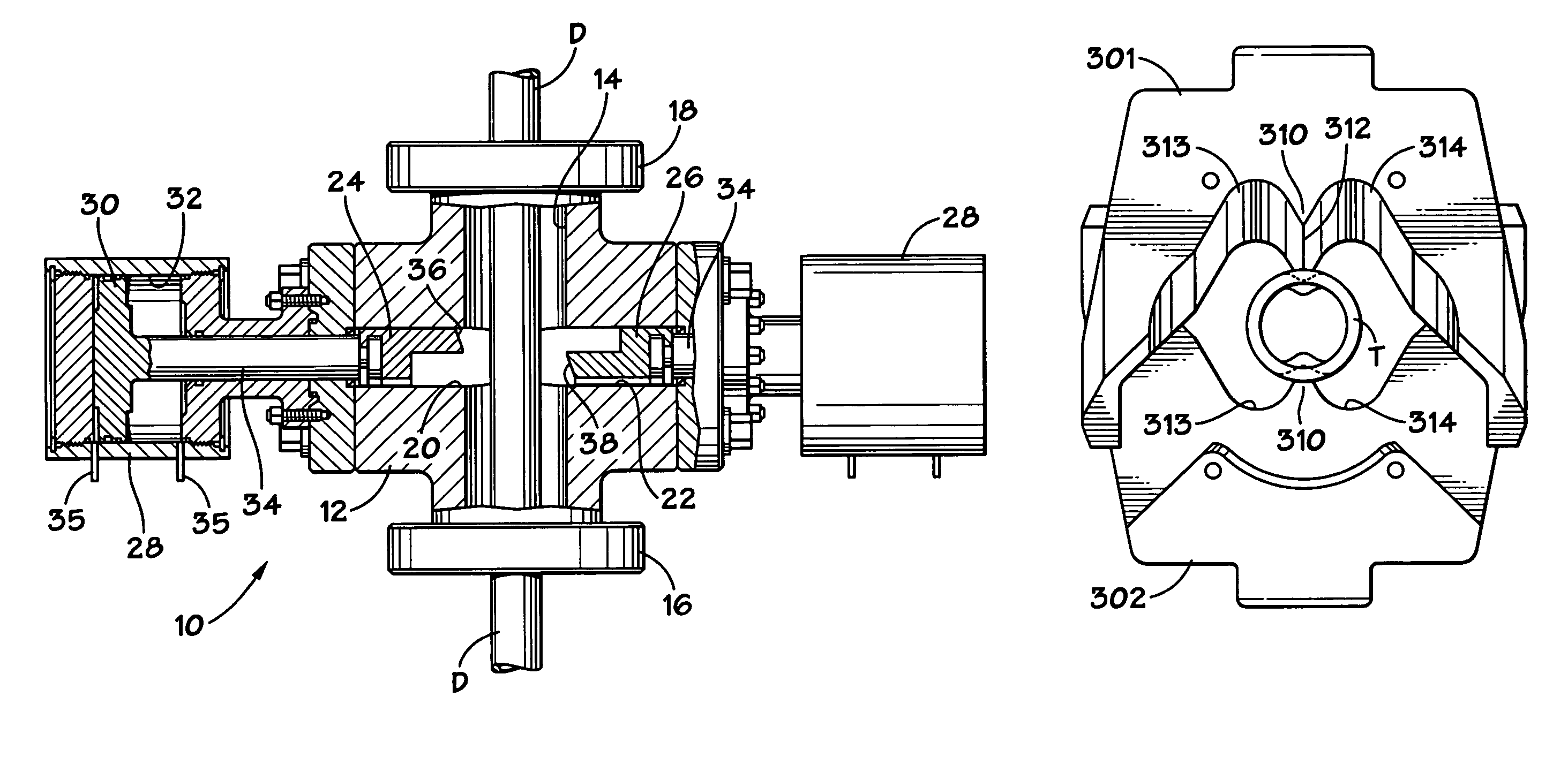
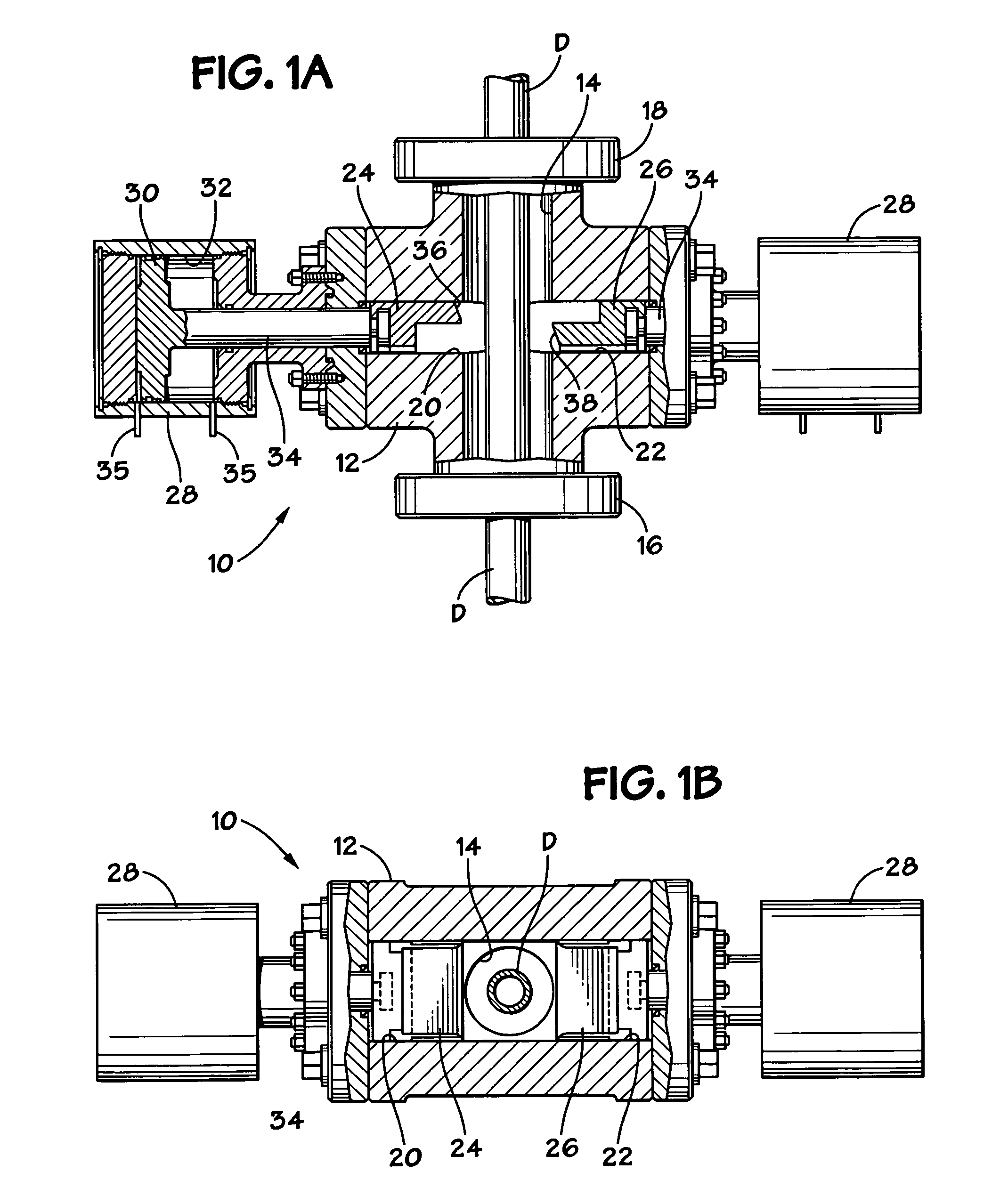
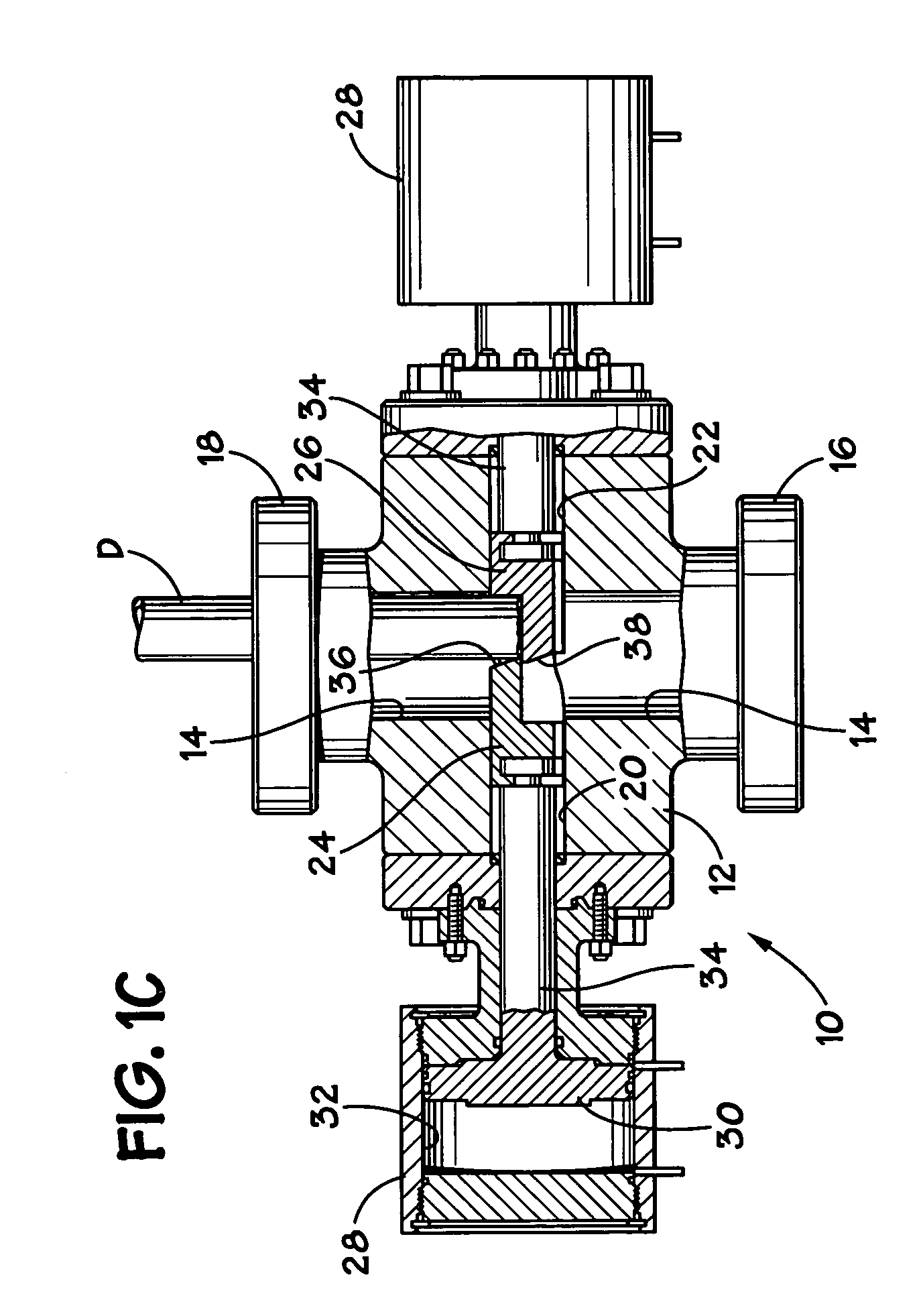
[0066]As shown in FIGS. 1A-1C, a blowout preventer 10 according to the present invention has a body 12 with a vertical bore 14 extending therethrough. A tubular, e.g. part of a drill string D passes through the bore 14. The body 12 has a lower flange 16 and an upper flange 18 for connecting the blowout preventer 10 in a wellhead stack. Ram guideways 20 and 22 extend outwardly from opposite sides of the bore 14. Ram assemblies of the blowout preventer 10 include first and second rams 24 and 26 which are positioned in guideways 20 and 22, respectively. Reciprocating apparatus, such as actuators 28, are provided to move or extend the rams in response to fluid pressure into the bore 14 for shearing the portion of the drill string D which extends through the bore and for retracting the rams from the bore. The actuators 28 each include a piston 30 in a cylinder 32 and a rod 34 connecting between the piston and the ram which it is to move and are suitably connected to body 12 as shown. Sui...


PUM

PropertyMeasurementUnit
angleaaaaaaaaaa
angleaaaaaaaaaa
angleaaaaaaaaaa

Abstract

Methods and apparatuses for severing a wellbore tubular, the apparatus, in certain aspects, including: a first member movable toward a tubular to be severed; a second member with a second blade disposed opposite to the first member and movable toward the tubular; a first blade on the first member having a projection projecting from a center of a blade body with point structure on the projection for puncturing the tubular and cutting surfaces on the projection for cutting the tubular; and cutting surfaces, as needed, on the blade body adjacent the projection for cutting the tubular.

Description

BACKGROUND OF THE INVENTION[0001]1. Field of the Invention[0002]This present invention is directed to blowout preventers, to tubular-shearing blades for them, and methods of their use.[0003]2. Description of Related Art[0004]The prior art discloses a wide variety of blowout preventers and tubular-shearing blades for blowout preventer bonnets.[0005]Typical blowout preventers have selectively actuatable rams in oppositely disposed bonnets secured to the body. The rams are either pipe rams (to contact, engage, and encompass pipe and / or tools to seal a wellbore) or shear rams (to contact and physically shear a tubular, casing, pipe or tool used in wellbore operations). Rams are usually positioned opposite each other on either side of a main body and can, upon activation and subsequent shearing of a tubular, seal against each other at a center of the main body over a center of a wellbore.[0006]Typical rams include a ram block on which parts, e.g. seals and / or cutting blades, are releasab...

Claims


Application Information

Patent Timeline
Patent Type & Authority Patents(United States)
IPC IPC(8): E21B29/08E21B29/00
CPCE21B33/063Y10T428/24777Y10T83/0581Y10T83/9447Y10T83/75Y10T83/0596
Inventor SPRINGETT, FRANK BENJAMINBRUGMAN, JAMES D.
Owner VARCO I P INC
Why Eureka
Try Eureka