Low profile rotating control device

a control device and low-profile technology, applied in the direction of drilling pipes, drilling/well accessories, sealing/packing, etc., can solve the problems of inability to rotate control devices, and inability to operate without a physical danger, so as to eliminate the need for physical danger and time-consuming work

Active Publication Date: 2012-10-16
WEATHERFORD TECH HLDG LLC
View PDF533 Cites 57 Cited by
  • Summary
  • Abstract
  • Description
  • Claims
  • Application Information

AI Technical Summary

Benefits of technology

[0024]A low profile RCD (LP-RCD) system and method for managed pressure drilling, underbalanced drilling, and for drilling with compressible fluids is disclosed. In several embodiments, the LP-RCD is positioned with a LP-RCD housing, both of which are configured to fit within the limited space available on some rigs, typically on top of a BOP. The lateral outlet or port in the LP-RCD housing for drilling fluid returns may have a flange having a diameter that is substantially the same as the height of the combined LP-RCD and LP-RCD housing. Advantageously, in one embodiment, an annular BOP seal is integral with a RCD housing so as to eliminate an attachment member, thereby resulting in a lower overall height of the combined BOP / RCD and easy access to the annular BOP seal upon removal of the RCD.
[0025]The ability to fit a LP-RCD in a limited space enables H2S and other dangerous gases to be being diverted away from the area immediately beneath the rig floor during drilling operations. The sealing element of the LP-RCD can be advantageously replaced from above, such as through the rotary table of the drilling rig, eliminating the need for physically dangerous and time consuming work under the drill rig floor. The LP-RCD enables smaller rigs with short substructure heights to drill with compressible fluids, such as air, mist, gas, or foam. One embodiment of the LP-RCD allows rotation of the inserted tubular about its longitudinal axis in multiple planes, which is beneficial if there is misalignment with the wellbore or if there are bent pipe sections in the drill string.

Problems solved by technology

However, some fluid reservoirs are considered economically undrillable with these conventional techniques.
Underbalanced drilling is drilling with the hydrostatic head of the drilling fluid intentionally designed to be lower than the pressure of the formations being drilled.
However, drilling must cease because movement of the drill string tubular will damage or destroy the non-rotatable annular seals.
However, smaller drilling rigs and structures are generally not equipped for managed pressure and / or underbalanced drilling because they lack pressure containment or management capability.
In some locations where such smaller rigs are used, such as in western Canada and parts of the northwestern and southeastern United States, there exist shallow pockets of H2S (sour gas), methane, and other dangerous gases that can escape to atmosphere immediately beneath the drill rig floor during drilling and / or workover operations.
Several blowouts have occurred in drilling and / or workovers in such conditions.
Even trace amounts of such escaping gases create health, safety, and environmental (HSE) hazards, as they are harmful to humans and detrimental to the environment.
Smaller drilling rigs and structures are also typically not able to drill with compressible fluids, such as air, mist, gas, or foam, because such fluids require pressure containment.
Also, HSE hazards could result without pressure containment, such as airborne debris, sharp sands, and toxins.
As discussed above, RCDs and their housings proposed in the prior art cannot fit on many smaller drilling rigs or structures due to the combined height of the RCDs and their housings, particularly if the rigs or structures already uses a BOP.

Method used


Image

  • Low profile rotating control device
  • Low profile rotating control device
  • Low profile rotating control device

Examples


Embodiment Construction

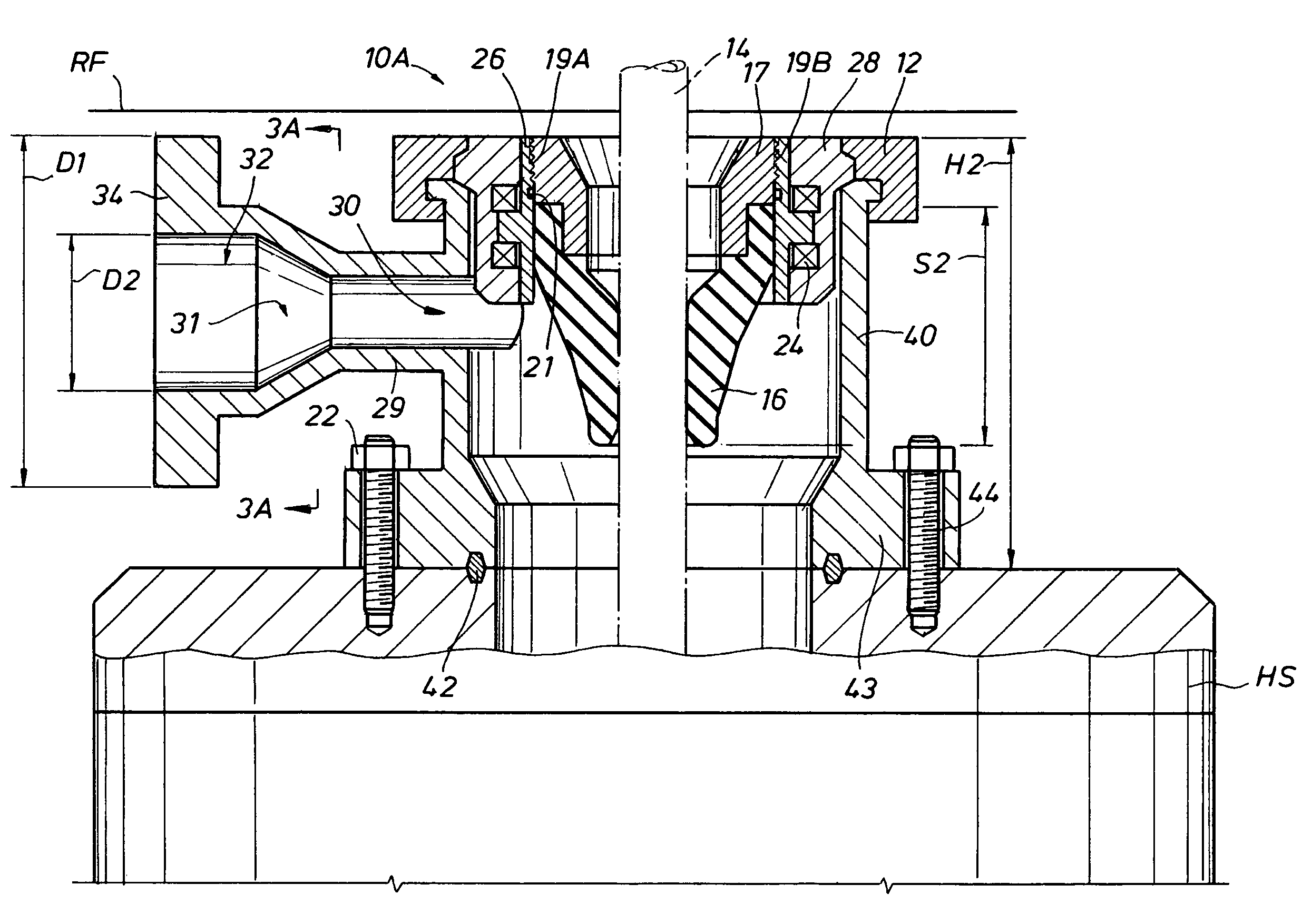
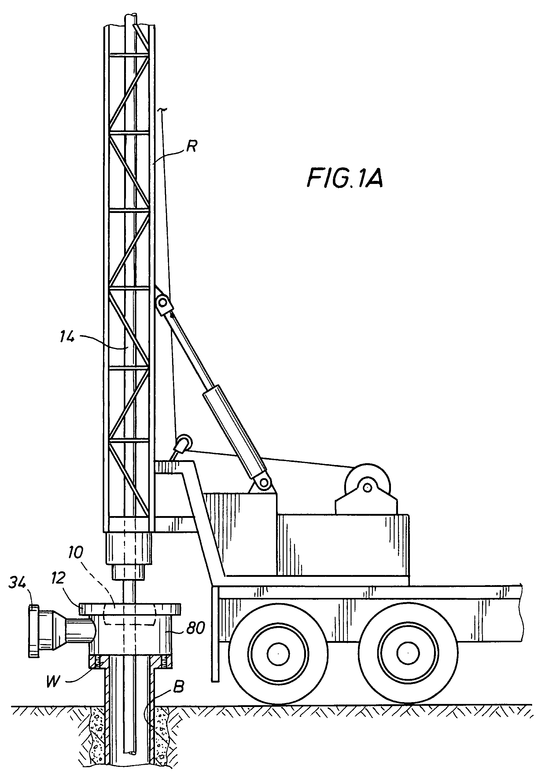
[0041]Generally, the present invention involves a system and method for converting a smaller drilling rig with a limited substructure height between a conventional open and non-pressurized mud-return system for hydrostatic pressure drilling, and a closed and pressurized mud-return system for managed pressure drilling or underbalanced drilling, using a low profile rotating control device (LP-RCD), generally designated as 10 in FIG. 1. The LP-RCD is positioned with a desired RCD housing (18, 40, 50, 80, 132, 172). The LP-RCD is further designated as 10A, 10B, or 10C in FIGS. 2-8 depending upon the type of rotation allowed for the inserted tubular (14, 110) about its longitudinal axis, and the location of its bearings. The LP-RCD is designated as 10A if it only allows rotation of the inserted tubular 14 about its longitudinal axis in a horizontal plane, and has its bearings 24 located inside of the LP-RCD housing (18, 40, 50, 172) (FIGS. 2-4, and 7-8), 10B if it allows rotation of the ...


PUM

PropertyMeasurementUnit
internal diameteraaaaaaaaaa
static pressureaaaaaaaaaa
heightsaaaaaaaaaa

Abstract

A system and method are provided for a low profile rotating control device (LP-RCD) and its housing mounted on or integral with an annular blowout preventer seal, casing, or other housing. The outer diameter of the lateral outlet flange may be substantially the same as the height of the LP-RCD housing and bearing assembly after the bearing assembly is positioned with the LP-RCD housing. The sealing element may be aligned with the lateral outlet, and may be replaced from above. Different embodiments of attachment members for attaching the LP-RCD housing with a lower housing allow the LP-RCD housing to be rotated to align the lateral outlet with the drilling rig's existing line to mud pits or other locations. In one embodiment, the LP-RCD bearings are positioned radially inside the LP-RCD housing. In another embodiment, the LP-RCD bearings are positioned radially outside the LP-RCD housing. One embodiment allows rotation of the inserted tubular about multiple planes. In still another embodiment, an annular BOP seal is integral with a RCD housing.

Description

CROSS-REFERENCE TO RELATED APPLICATIONS[0001]N / ASTATEMENT REGARDING FEDERALLY SPONSORED RESEARCH OR DEVELOPMENT[0002]N / AREFERENCE TO MICROFICHE APPENDIX[0003]N / ABACKGROUND OF THE INVENTION[0004]1. Field of the Invention[0005]This invention relates to the field of fluid drilling equipment, and in particular to rotating control devices to be used in the field of fluid drilling equipment.[0006]2. Description of the Related Art[0007]Conventional oilfield drilling typically uses hydrostatic pressure generated by the density of the drilling fluid or mud in the wellbore in addition to the pressure developed by pumping of the fluid to the borehole. However, some fluid reservoirs are considered economically undrillable with these conventional techniques. New and improved techniques, such as underbalanced drilling and managed pressure drilling, have been used successfully throughout the world. Managed pressure drilling is an adaptive drilling process used to more precisely control the annular...

Claims


Application Information

Patent Timeline
Patent Type & Authority Patents(United States)
IPC IPC(8): E21B33/03
CPCE21B7/02E21B21/106E21B33/085E21B33/06Y10T29/49815E21B2021/006E21B21/085E21B21/08E21B33/068
Inventor HANNEGAN, DON M.BAILEY, THOMAS F.CHAMBERS, JAMES W.WOODRUFF, DAVID R.HARRALL, SIMON J.
Owner WEATHERFORD TECH HLDG LLC
Why Eureka
Try Eureka