Four wheel mechanical brake system for inline skates

a brake system and inline skate technology, applied in the direction of skateboards, roller skates, skating, etc., can solve the problems of increasing instability, rolling on one wheel with one skate becoming an unstable position, and limiting the use of inline skate brakes presently in use, so as to achieve maximum braking

Inactive Publication Date: 2008-05-06
LANSEL TOBY
View PDF13 Cites 3 Cited by
  • Summary
  • Abstract
  • Description
  • Claims
  • Application Information

AI Technical Summary

Benefits of technology

[0006]This invention seeks to provide smooth and effective braking on one or both skates without having to lift the front of the skate off the ground.
[0013]The spring tension is adjustable so that maximum braking can be achieved for skaters with different body weights without the wheels locking up and skidding.

Problems solved by technology

Inline skate brakes presently in use are almost exclusively limited to a piece of rubber mounted behind the heel of one of the skates.
Rolling on one wheel with one skate becomes an unstable position.
This instability is further increased when scraping the rubber piece on the ground.
One improved brake system uses a lever device to push the rubber piece to the ground when the lower leg is straightened without having to lift the front of the skate, thus rolling on all wheels, greatly improving stability, but still having rough and ineffective braking.

Method used


Image

  • Four wheel mechanical brake system for inline skates
  • Four wheel mechanical brake system for inline skates
  • Four wheel mechanical brake system for inline skates

Examples


Embodiment Construction

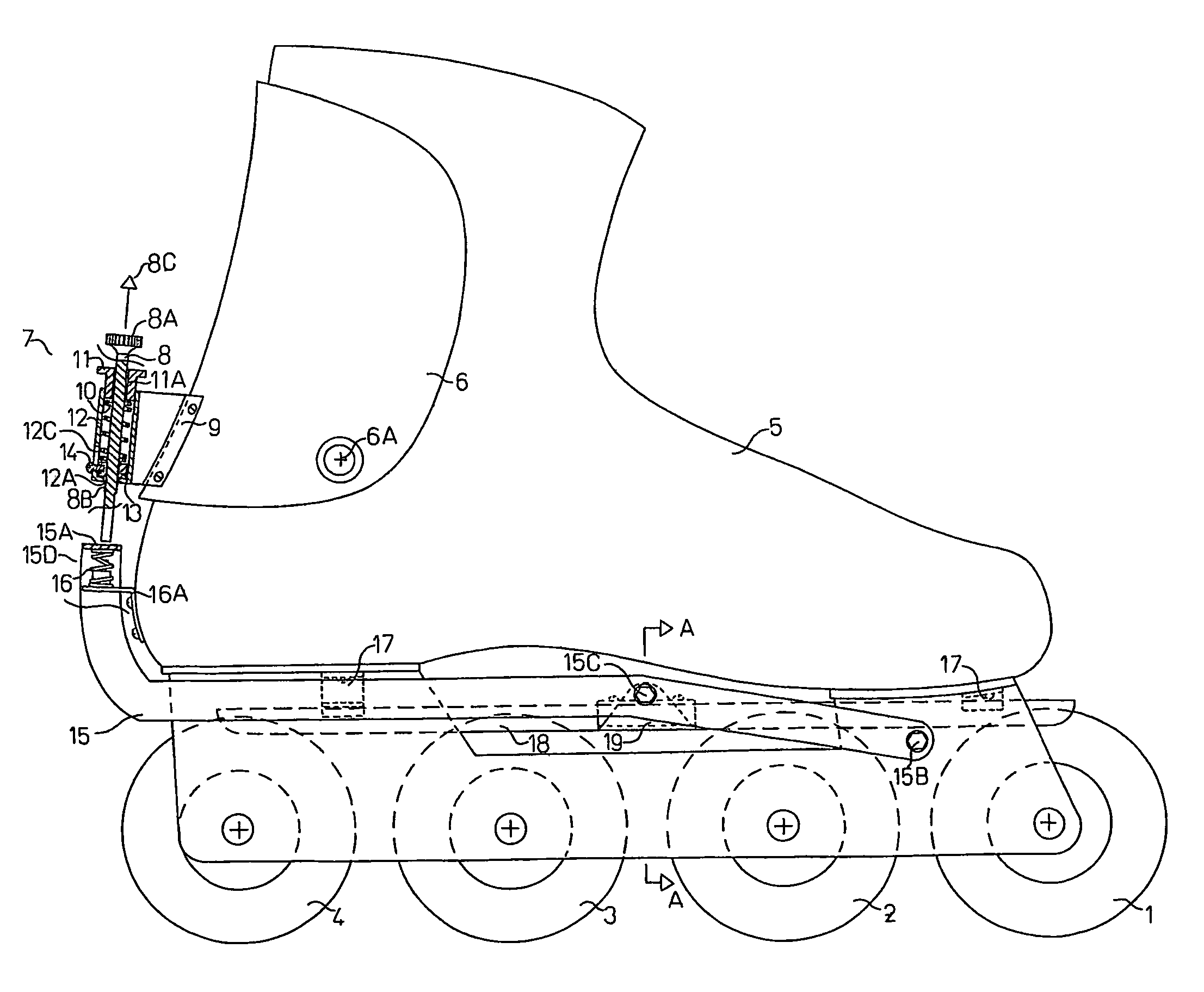
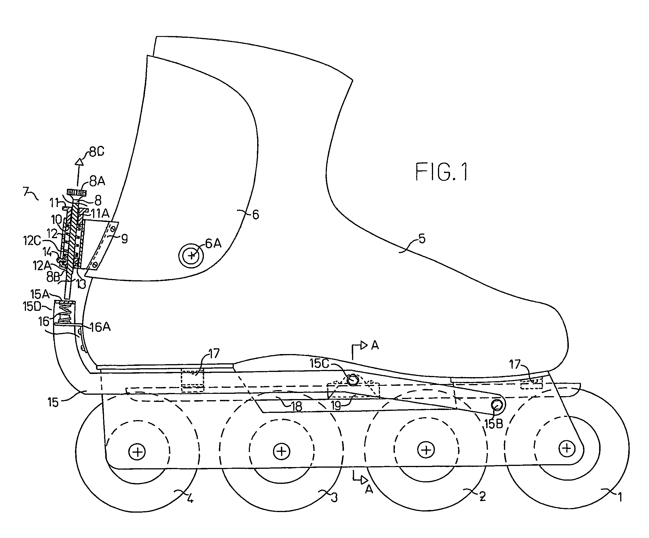
[0018]In FIG. 1, 5 indicates an elevational side view of an inline skate with the herein described “four wheel mechanical brake system” disengaged.

[0019]1, 2, 3 and 4 indicate the skate wheels.

[0020]6 is the pivoting ankle support.

[0021]6A is the pivot point.

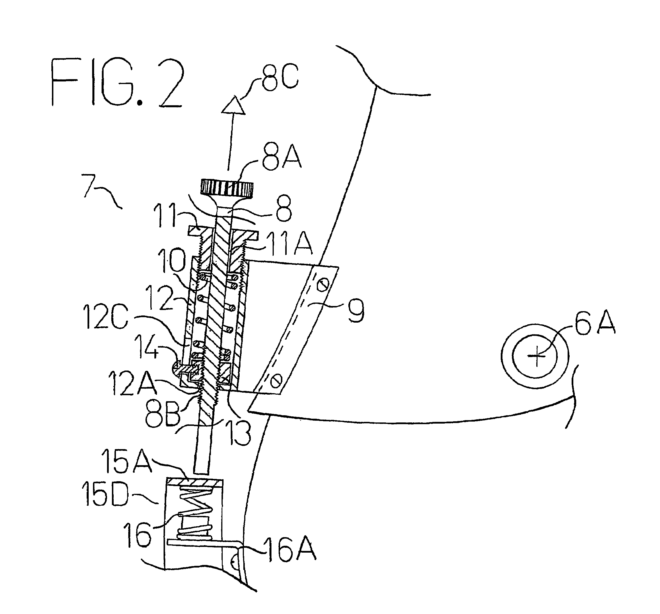
[0022]See FIG. 2 for greater clarity of detail of the trigger assembly.

[0023]7 is a lengthwise sectional view of the trigger assembly.

[0024]8 is the trigger rod.

[0025]8A is the adjustment knob of the trigger rod.

[0026]8B is the threaded lower portion of the trigger rod. The arrow 8C indicates the direction of movement of the trigger rod, when the trigger spring 10 becomes somewhat compressed during braking.

[0027]9 is the mounting bracket for the trigger assembly.

[0028]10 is the trigger spring.

[0029]11 is the trigger spring adjustment nut.

[0030]11A is the center hole in the trigger spring adjustment nut that accommodates the vertical movement of the trigger rod 8.

[0031]12 is the tubular spring housing.

[0032]12A is a hole in the b...


PUM


Abstract

A mechanical brake system for inline skates that utilizes all four wheels for braking. The brake is applied by the skater straightening the leg, or both legs if there are brakes on both skates, to a predetermined adjustable position. This causes the adjustable and spring loaded trigger rod, mounted on the pivoting ankle support behind the heel to push the brake lever that extends from behind the heel on both sides of the frame to the front where it is hingedly attached to move downwards. At the mid-point of the skate the brake rail positioned above the wheels and extending the whole length of the skate is connected to the brake lever. The downward movement of the brake lever and brake rail causes the brake rail to contact the wheels causing friction and thereby braking in direct proportion to the force by which the skater is straightening the leg(s). The brake rail is inflexible and shaped to fit the curvature of the wheels thereby facilitating even wheel wear both regarding shape and diameter. Two brackets mounted on the underside of the skate and passing through slots in the brake rail ensure centering of the brake rail. The spring loading of the trigger rod ensures smooth and controllable braking. The spring tension of the spring loaded trigger rod is adjustable so that skaters with different body weight can have optimum braking power without wheel lock-up.

Description

BACKGROUND ART[0001]This invention relates to a brake system for inline skates and seeks to improve the inline skaters stability when braking, and also to provide smooth and effective braking.[0002]Inline skate brakes presently in use are almost exclusively limited to a piece of rubber mounted behind the heel of one of the skates.[0003]In order to brake, the skater has to lift the front of the skate thus having only one wheel rolling on the ground while pushing the rubber piece to the ground.[0004]Rolling on one wheel with one skate becomes an unstable position. This instability is further increased when scraping the rubber piece on the ground.[0005]One improved brake system uses a lever device to push the rubber piece to the ground when the lower leg is straightened without having to lift the front of the skate, thus rolling on all wheels, greatly improving stability, but still having rough and ineffective braking.DISCLOSURE OF THE INVENTION[0006]This invention seeks to provide smo...

Claims


Application Information

Patent Timeline
Patent Type & Authority Patents(United States)
IPC IPC(8): A63C17/14
CPCA63C17/1418A63C17/06A63C2017/1481
Inventor LANSEL, TOBY
Owner LANSEL TOBY
Why Eureka
Try Eureka