Method and apparatus for controlling the sheet feeding speed in a printer

a printing machine and feeding speed technology, applied in the field of printing machines, can solve the problems of not considering differences, unnecessarily longening and the time required to print becomes longer, so as to reduce the feeding speed and reduce the feeding speed

Active Publication Date: 2008-05-06
BROTHER KOGYO KK
View PDF8 Cites 7 Cited by
  • Summary
  • Abstract
  • Description
  • Claims
  • Application Information

AI Technical Summary

Benefits of technology

[0012]Depending on the type of the cut sheet, sometimes it is not necessary to reduce the feeding speed at a time when the leading edge of the cut sheet contacts the sending rollers. Alternatively, depending on the type of printing mode, it is not necessary to reduce the feeding speed at a time when the leading edge of the cut sheet contacts the sending rollers.
[0014]If the feeding speed of the cut sheet is reduced before the leading edge of the cut sheet contacts the sending rollers, the time required for printing becomes longer. The printer in Japanese Laid-Open Patent Application Publication No. 1998-254202 unnecessarily lengthens the time required to print in a case where there is no need to reduce the feeding speed.
[0019]The printer of the present invention reduces a feeding speed before a leading edge of a cut sheet contacts a pair of sending rollers for occasions when problems will arise unless it decelerates, and does not reduce the feeding speed for occasions when problems will not arise even if it does not decelerate. It does not unnecessarily lengthen the time required to print due to decelerating even when unnecessary. Alternatively, in other cases, a slant-adjusting phenomenon can be obtained when necessary.
[0024]This controlling method provides a step of identifying a timing when the leading edge of the cut sheet is fed to a predetermined position upstream of the sending rollers for a predetermined distance and, when a predetermined condition is satisfied, a step of reducing the speed of the feeder at a timing identified by the above identifying step.
[0026]According to this printer, when the predetermined condition is satisfied, a high-quality printing image can be obtained because the leading edge of the cut sheet contacts the sending rollers in a situation where the speed has been reduced to a point in which the leading edge of the cut sheet does not get damaged by the sending rollers.

Problems solved by technology

However, the printer described in Japanese Laid-Open Patent Application Publication No. 1998-254202 does not consider differences among various types of cut sheets.
Further, it does not consider differences among various types of printing modes.
If the feeding speed of the cut sheet is reduced before the leading edge of the cut sheet contacts the sending rollers, the time required for printing becomes longer.
The printer in Japanese Laid-Open Patent Application Publication No. 1998-254202 unnecessarily lengthens the time required to print in a case where there is no need to reduce the feeding speed.
While a single cut sheet is pulled out from a stack of cut sheets and fed toward a pair of sending rollers, there are occasions when the position of the cut sheet is out of alignment.
In contrast, if the feeding speed is low when the leading edge of the cut sheet contacts the sending rollers, the leading edge of the cut sheet cannot be adjusted to become parallel with the sending rollers.

Method used


Image

  • Method and apparatus for controlling the sheet feeding speed in a printer
  • Method and apparatus for controlling the sheet feeding speed in a printer
  • Method and apparatus for controlling the sheet feeding speed in a printer

Examples


Embodiment Construction

[0037]A multifunctional device incorporating a printer practicing the present invention will be explained with reference to the figures.

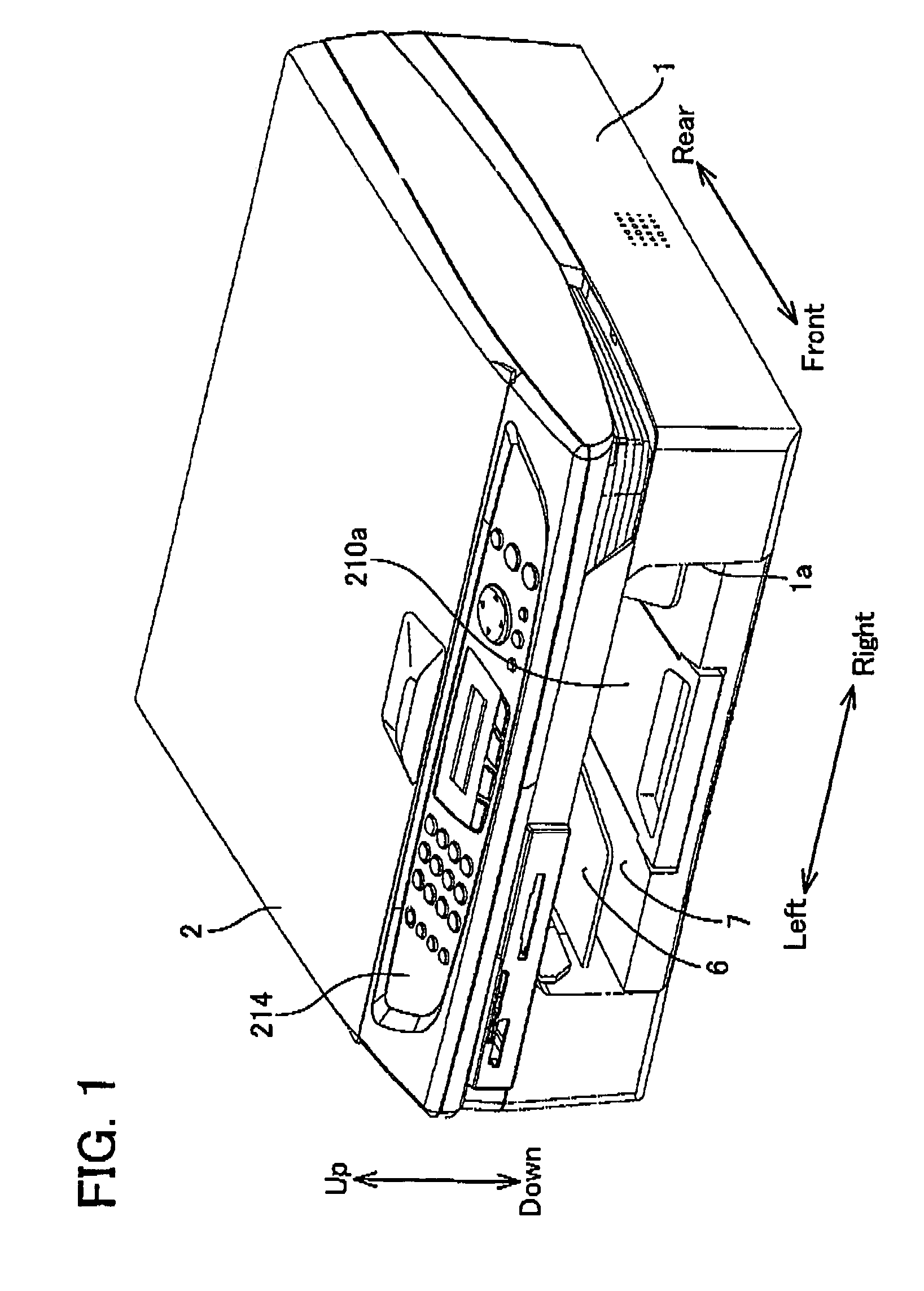
[0038]The multifunctional device (abbreviated as MFD hereinafter) of the present embodiment provides a printing function, copying function, scanning function, and facsimile function. As shown in FIG. 1 and FIG. 3, image reading device 2 for the copying function or the scanning function is set up on an upper surface of main body frame 1 made of plastic injection molding item. Internally of the MFD, printer 99 is incorporated in a position below image reading device 2.

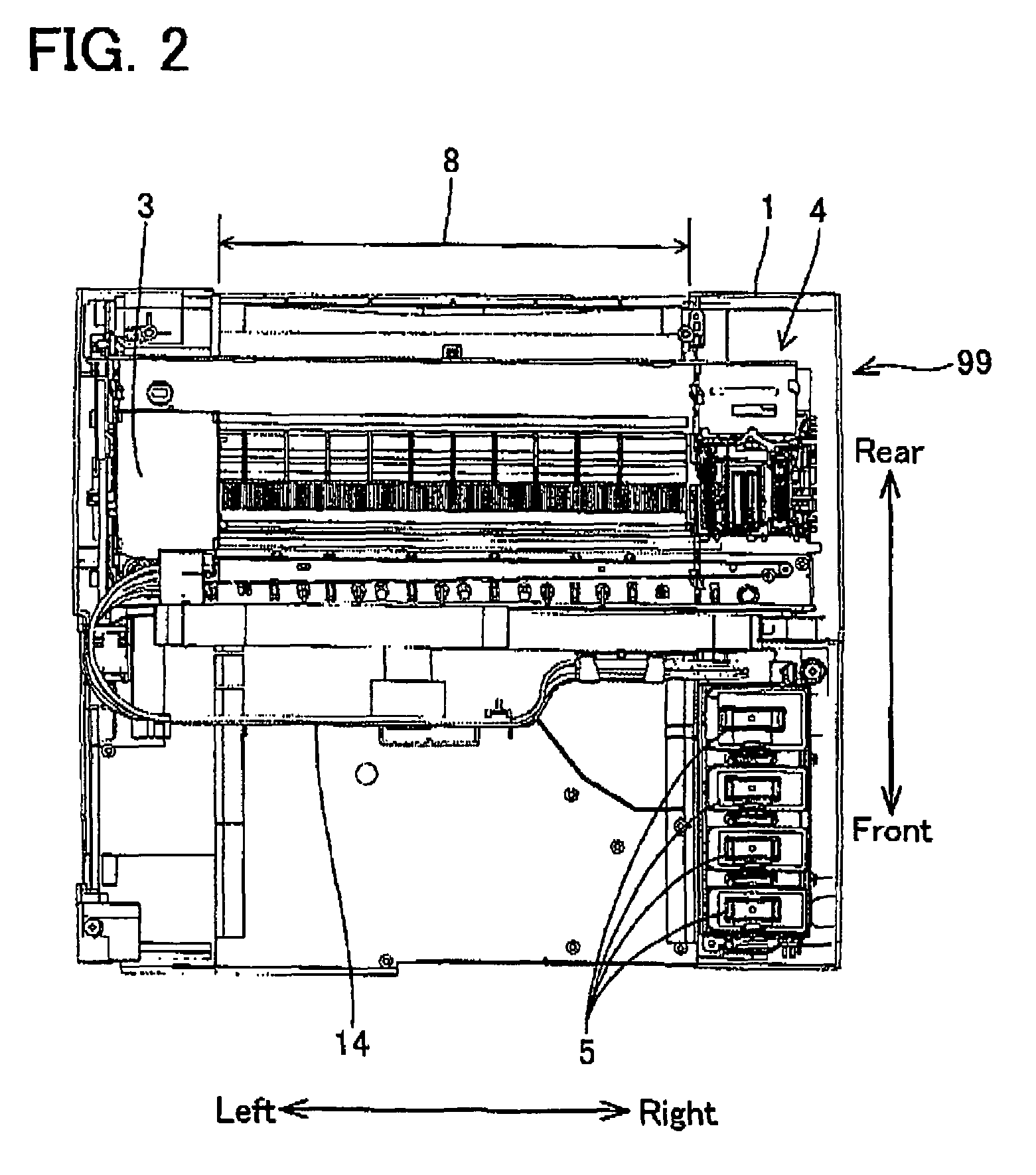
[0039]As shown in FIG. 2 and FIG. 3, printer 99 provides carriage 3, movable in a round-trip fashion in a right-left direction. As shown in FIG. 3, printing head 10, which prints images or characters, is fixed on carriage 3. As shown in FIG. 2, printer 99 provides maintenance unit 4, and maintenance unit 4 recovers the clogging of nozzles of printing head 10. Ink tank 5 to supply ink to ...


PUM


Abstract

In order to adjust a position of a cut sheet when the cut sheet begins to be sent to a printing positions a leading edge of the cut sheet is fed towards a pair of sending rollers for sending the cut sheet to a printing position, wherein the sending rollers are held at rest or rotated in reverse. If a predetermined condition is satisfied, a feeding speed of the cut sheet decreases when the leading edge of the cut sheet reaches a position that is a predetermined distance upstream of the sending rollers. If the predetermined condition is not satisfied, the feeding speed of the cut sheet does not decrease before the leading edge of the cut sheet contacts the sending roller. A decline in printing quality and an unnecessary delay in printing time can be prevented. With the sending rollers, an effect to prevent the leading edge of the cut sheet from being fed in a slanted position is also maintained.

Description

CROSS-REFERENCE TO RELATED APPLICATION[0001]This application claims priority to Japanese Patent Application No. 2004-283310 filed on Sep. 29, 2004, the contents of which are hereby incorporated by reference into the present application.BACKGROUND OF THE INVENTION[0002]1. Field of the Invention[0003]The present invention relates to a printer that separates a single cut sheet from a stack of cut sheets, feeds the separated sheet and prints on the cut sheet. A printer of the present invention provides a printing head to print on the cut sheet at a printing position and a pair of sending rollers to send the cut sheet to the printing position. The printer of the present invention can control the position of the cut sheet when the cut sheet begins to be sent to the printing position, and can control a relationship between the timing of when to begin sending the cut sheet to the printing position and the timing of when to have the printing head begin a printing operation. According to the ...

Claims


Application Information

Patent Timeline
Patent Type & Authority Patents(United States)
IPC IPC(8): B65H7/02
CPCB41J11/0065B41J11/425
Inventor KOGA, YUJIKOIDE, SHOHEIOUCHI, TETSUYA
Owner BROTHER KOGYO KK
Why Eureka
Try Eureka