Motor drive control device for limiting output of motor

a control device and motor technology, applied in the direction of electric controllers, program control, instruments, etc., can solve the problems of adverse effects the inability to effectively limit the sum of the output of servo motors and the output of spindle motors, and the adverse impact on the cutting operation of workpieces by machine tools. , to achieve the effect of not limiting the torque of spindle motors, limiting the torque of spind

Active Publication Date: 2014-04-15
FANUC LTD
View PDF10 Cites 5 Cited by
  • Summary
  • Abstract
  • Description
  • Claims
  • Application Information

AI Technical Summary

Benefits of technology

[0014]Preferably, the first control unit or the second control unit monitors a DC link voltage between the rectifier unit and the first inverter unit or between the rectifier unit and the second inverter unit and provides information about the DC link voltage to an upper control device, and the first control unit controls the alternating-current power of the first inverter unit so as to reduce the feed speed of at least one feed axis of the machine tool in response to a feed speed reduction command issued from the upper control device if the upper control device predicts that the sum of the output of the servo motor and the output of the spindle motor exceeds the electric power, which can be supplied by the rectifier unit, during the cutting operation, based on the DC link voltage.
[0017]According to an aspect of the present invention, if it is predicted that the sum of the output of the servo motor and the output of the spindle motor exceeds the electric power, which can be supplied by the rectifier unit, during the cutting operation of a workpiece by the machine tool, the alternating-current power of the first inverter unit is controlled so at to reduce the feed speed of at least one feed axis of the machine tool and at the same time, the alternating-current power of the second inverter unit is controlled so as not to limit the torque of the spindle motor. Further, if it is predicted that the sum of the output of the servo motor and the output of the spindle motor exceeds the electric power, which can be supplied by the rectifier unit, during an operation other than the cutting operation of a workpiece by the machine tool, the alternating-current power of the second inverter unit is controlled so as to limit the torque of the spindle motor so as not to reduce the feed speed. By reducing the feed speed of the feed axis during the cutting operation of a workpiece by the machine tool as described above, the output required by the spindle motor is reduced as a result. Thereby, the output of the spindle motor remarkably larger than the output of the servo motor reduces sufficiently and it is possible to effectively limit the sum of the output of the servo motor and the output of the spindle motor, and therefore, it is possible to limit the output of the motor without adversely affecting the cutting operation of a workpiece by the machine tool.

Problems solved by technology

However, it is rare that the servo motor and the spindle motor reach the maximum output at the same time, and therefore, the electric power, which can be supplied by the rectifier unit, is usually set to an output supposed to be smaller than the sum of the maximum output of the servo motor and the maximum output of the spindle motor from the viewpoint of the installation space and cost of the rectifier unit.
If the torque of the servo motor is limited in order to limit the sum of the output of the servo motor and the output of the spindle motor, the ratio of the output of the servo motor to the sum of the output of the servo motor and the output of the spindle motor is remarkably small (for example, 10%), and therefore, it is difficult to effectively limit the sum of the output of the servo motor and the output of the spindle motor.
Further, if the torque of the servo motor is limited in order to limit the sum of the output of the servo motor and the output of the spindle motor, there may be a case where the cutting operation of a workpiece by the machine tool is adversely affected because of deterioration of tracking of the position command to the servo motor.
On the other hand, if the torque of the spindle motor is limited in order to limit the sum of the output of the servo motor and the output of the spindle motor, there may be a case where the cutting operation of a workpiece by the machine tool is affected adversely when it is no longer possible to continue the cutting operation because of the stop of the spindle motor due to the shortage of torque during the cutting operation of a workpiece by the machine tool, in particular, during the cutting operation of a heavy workpiece.

Method used


Image

  • Motor drive control device for limiting output of motor
  • Motor drive control device for limiting output of motor
  • Motor drive control device for limiting output of motor

Examples


first embodiment

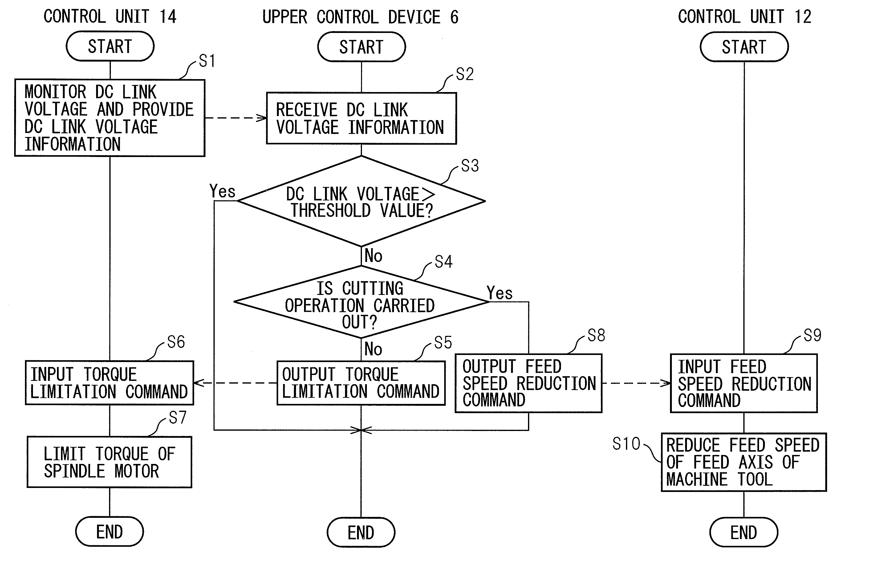
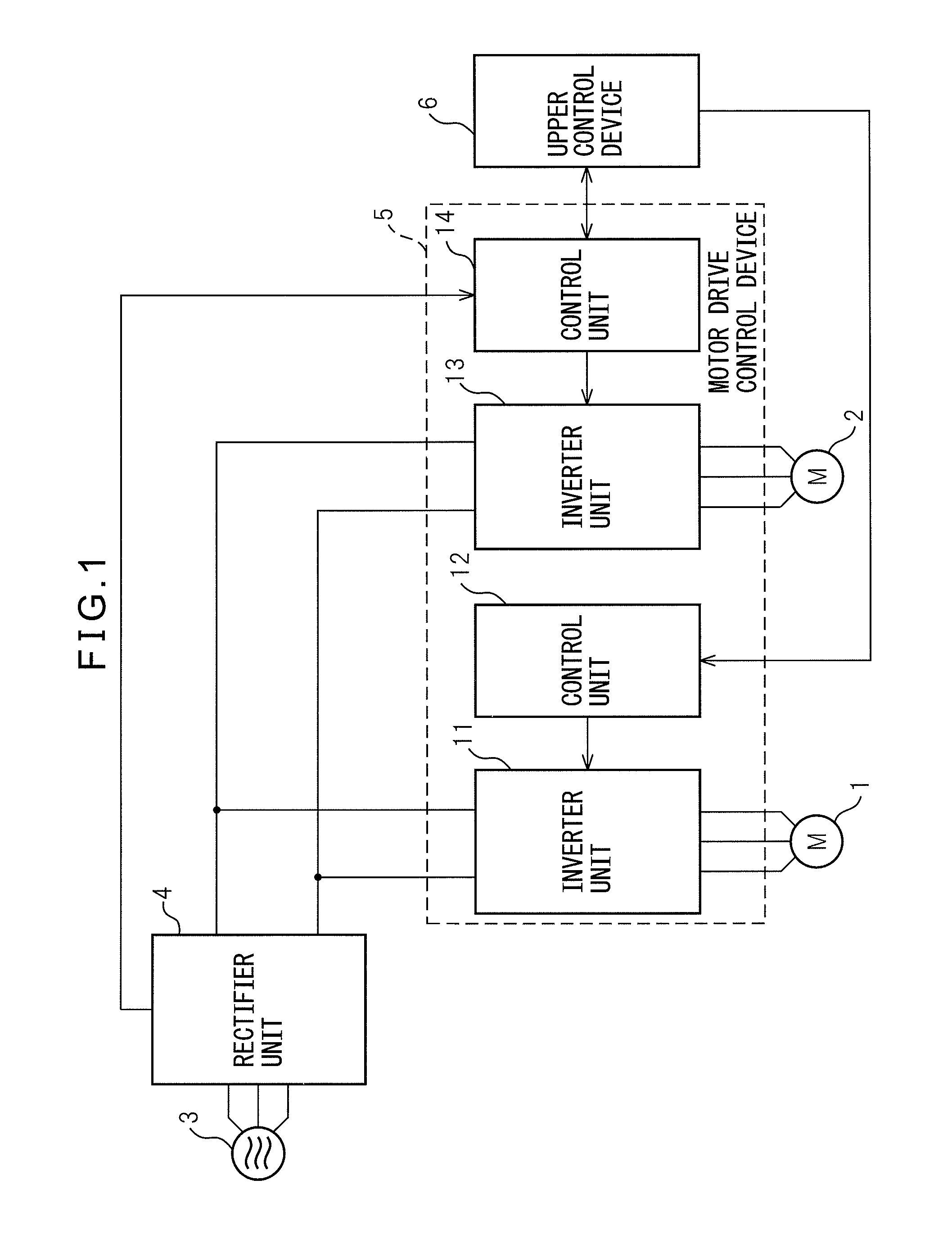
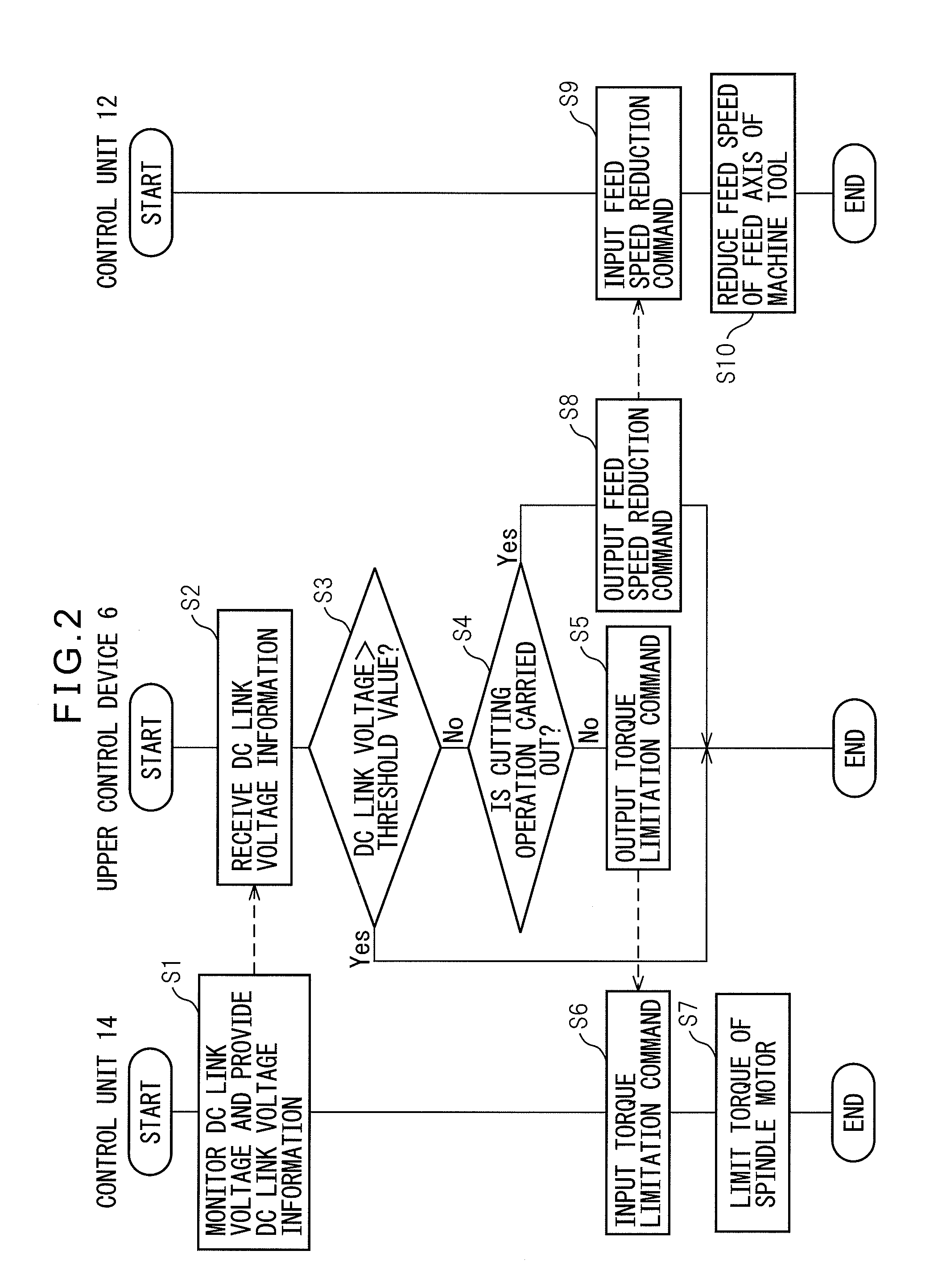
[0025]Referring to the drawings, FIG. 1 is a block diagram of a system having a motor drive control device according to the present invention. The system shown in FIG. 1 is used to drive and control at least one servo motor 1 configured to drive one feed axis to move a table or tool of a machine tool and a spindle motor 2 having a fist main axis to rotate a table or tool of a machine tool. To do this, the system shown in FIG. 1 has a three-phase alternating-current power source 3, a rectifier unit 4, a motor drive control device 5, and an upper control device 6. In FIG. 1, one servo motor 1 is shown, however, it may also be possible to provide two or more servo motors 1 and to drive at least two feed axes perpendicular to each other to move the table or tool of the machine tool.

[0026]The three-phase alternating-current power source 3 is configured by a commercial alternating-current power source. The rectifier unit 4 converts an Alternating-current voltage of alternating current sup...

second embodiment

[0052]FIG. 4 is a block diagram of a system having a motor drive control device according to the present invention. The system shown in FIG. 4 is used to drive and control at least one servo motor 1 configured to drive one feed axis to move a table or tool of a machine tool and the spindle motor 2 having one main axis to rotate the table or tool of the machine tool. To do this, the system shown in FIG. 4 has the three-phase alternating-current power source 3, the rectifier unit 4, a motor drive control device 5′, and the upper control device 6. In FIG. 4 also, one servo motor 1 is shown, however, it may also be possible to provide two or more servo motors 1 and to drive at least two feed axes perpendicular to each other to move the table or tool of the machine tool.

[0053]In FIG. 4, the three-phase alternating-current power source 3, the rectifier unit 4, and the upper control device 6 have the same configurations as those of the three-phase alternating-current power source 3, the re...


PUM


Abstract

If it is predicted that the sum of the output of a servo motor and the output of a spindle motor exceeds power supplied by a rectifier unit, during a cutting operation, a motor drive control device controls alternating-current power of a first inverter unit so as to reduce the feed speed of at least one feed axis and controls alternating-current power of a second inverter unit so as not to limit torque of the spindle motor. Further, if it is predicted that the sum of the output of the servo motor and the output of the spindle motor exceeds power supplied by the rectifier unit, during an operation other than the cutting operation, the motor drive control device controls the alternating-current power of the second inverter unit so as to limit the torque so as not to reduce the feed speed.

Description

RELATED APPLICATIONS[0001]The present application is based on, and claims priority from, Japanese Application Number 2012-018839, filed Jan. 31, 2012, the disclosure of which is hereby incorporated by reference herein in its entirety.BACKGROUND OF THE INVENTION[0002]1. Field of the Invention[0003]The present invention relates to a motor drive control device for driving and controlling at least one servo motor configured to drive one feed axis to move a table or tool of a machine tool and one spindle motor having one main axis to rotate a table or tool of a machine tool.[0004]2. Description of Related Art[0005]In such a motor drive control device, in order to drive and control a servo motor and a spindle motor, alternating-current voltage or alternating current from a commercial alternating-current power source, such as a three-phase alternating-current power source, is converted into direct-current voltage or direct current and then, converted into alternating-current voltage or alt...

Claims


Application Information

Patent Timeline
Patent Type & Authority Patents(United States)
IPC IPC(8): H02P5/74
CPCH02P5/74
Inventor OKITA, TADASHITAJIMA, DAISUKE
Owner FANUC LTD
Why Eureka
Try Eureka