Ceramic bit for high speed drilling

a ceramic bit and high-speed technology, applied in the direction of twist drills, manufacturing tools, wood boring tools, etc., can solve the problems of limited utilization of ceramic bits, difficult to provide ceramic bits for drilling at very high speeds in very hard materials, and greater stress that can be applied to drill bits during drilling operations, etc., to achieve high speed, improve the performance of ceramic bits, and simple and inexpensive

Active Publication Date: 2008-05-06
SN DETUDE & DE CONSTR DE MOTEURS DAVIATION S N E C M A
View PDF14 Cites 22 Cited by
  • Summary
  • Abstract
  • Description
  • Claims
  • Application Information

AI Technical Summary

Benefits of technology

[0006]An object of the invention is to avoid the above-mentioned drawbacks and to provide a solution that is technically simple and inexpensive, that enables the performance of ceramic bits to be improved, and that enables hard materials to be drilled at very high speed.

Problems solved by technology

Unfortunately, the stresses that can be applied to a drill bit (drilling depth, swarf removal, intensity and direction of cutting forces) during a drilling operation are greater than those that might be applied, for example, to a lathe tool or to a cutter during a milling operation.
These stresses make it more difficult to provide ceramic bits for drilling at very high speeds in very hard materials.
Although those bits provide improved performance compared with conventional bits made of high-speed steel or of tungsten carbide, they are limited in their utilizations and they do not enable very high speed drilling to be performed in materials as hard as superalloys.
Because of the low toughness of ceramic materials, ceramic bits present lower torsional strength and compressive strength than metallic bits, e.g. made of tungsten carbide, with these mechanical characteristics causing ceramic bits to be brittle when drilling in hard materials or when drilling at high speeds of advance or at high cutting speeds.
Nevertheless, such bits are still of limited use in terms of the materials they can drill and of the cutting and advance speeds of the bits.
When drilling materials as hard as refractory materials such as superalloys based, for example, on nickel and cobalt (having a Vickers hardness number of about 440) and when the cutting and advance speeds are very high, for example when the cutting speed is greater than about 400 meters per minute (m / min) and when the speed of advance is greater than 0.04 millimeters per revolution, the twisting and axial compression forces that are generated and applied to prior art bits are such that they will inevitably break.
In addition, the cutting forces exerted by such bits on the workpieces to be drilled, and the friction between the radially-outer surfaces of the bits and the inner cylindrical surfaces of the drilled holes lead to thermal stresses in the bits and the workpieces to be drilled that cause accelerated degradation of the bits and deformation of the workpiece when attempts are made to drill at high speed in very hard materials.
In addition, with increasing depth of a hole being drilled, the twisting forces applied to ceramic bits become ever greater, firstly because there is an ever increasing outside area of the bit rubbing against the inner cylindrical surface of the drill hole, and secondly because when drilling at high speeds, prior art ceramic bits cannot evacuate a large quantity of swarf efficiently, thereby leading to clogging phenomena in the bit, and consequently increasing the twisting forces applied to the bit and increasing the risks of it breaking.
These drawbacks generally make it impossible to drill holes at high speed to a depth that is greater than the diameter of the bit.

Method used


Image

  • Ceramic bit for high speed drilling
  • Ceramic bit for high speed drilling
  • Ceramic bit for high speed drilling

Examples


Embodiment Construction

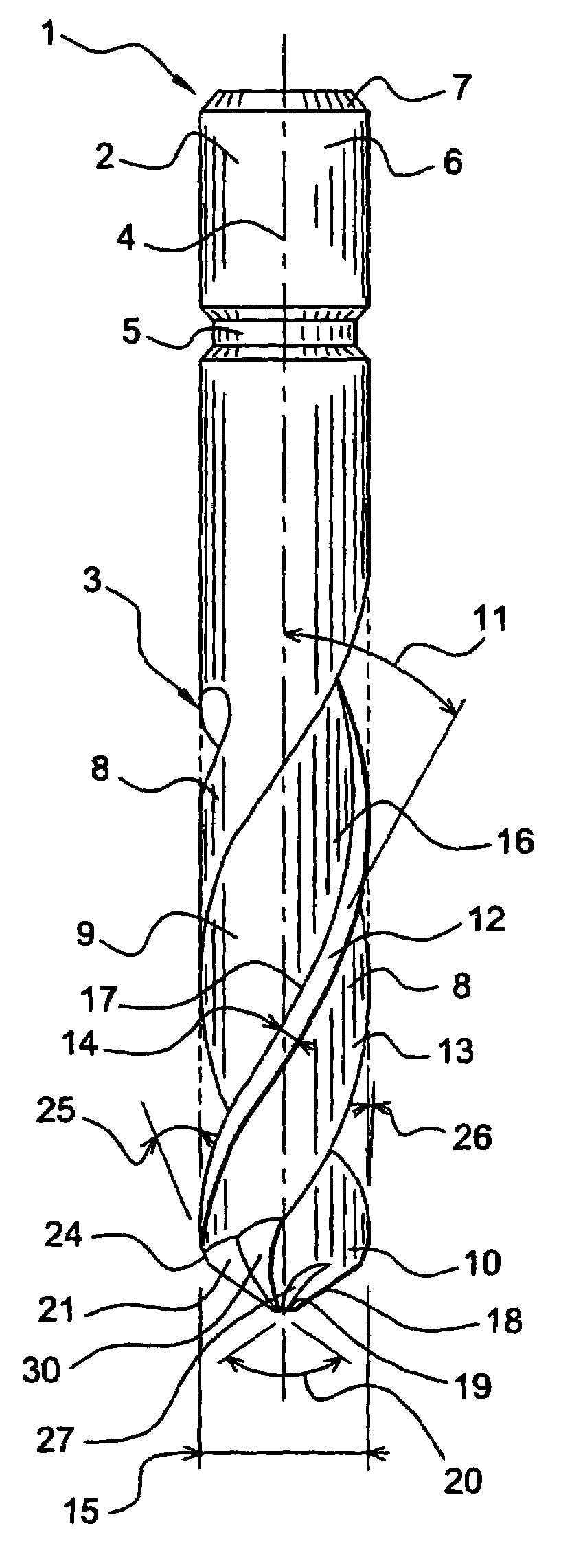
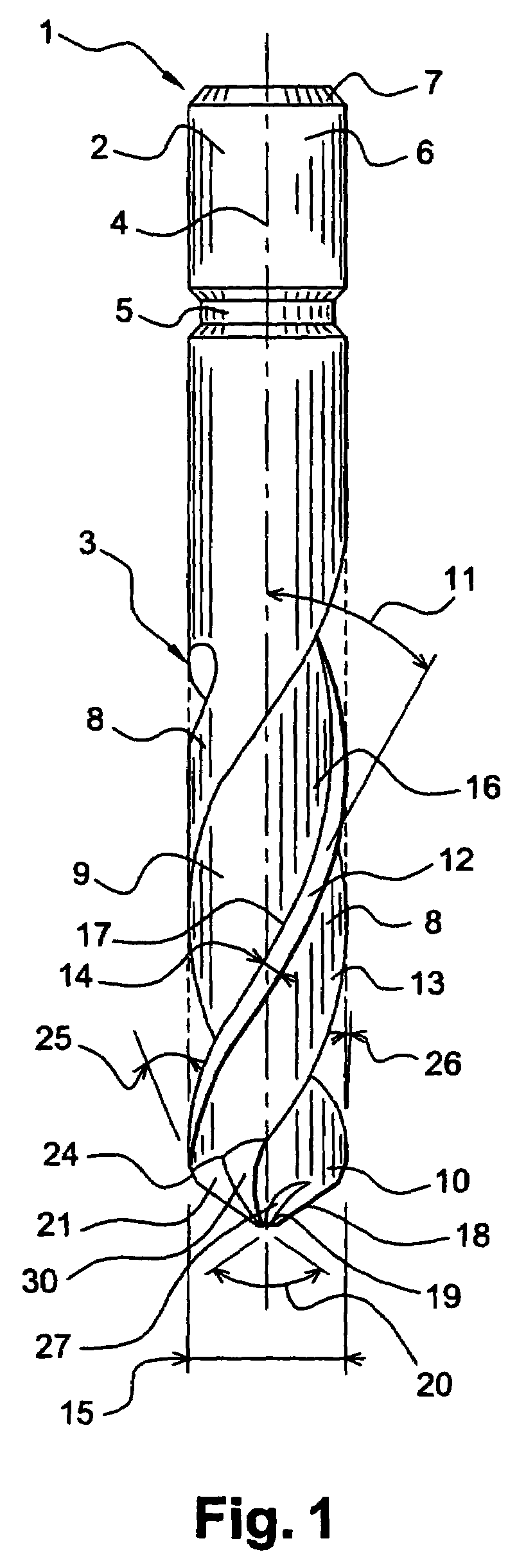
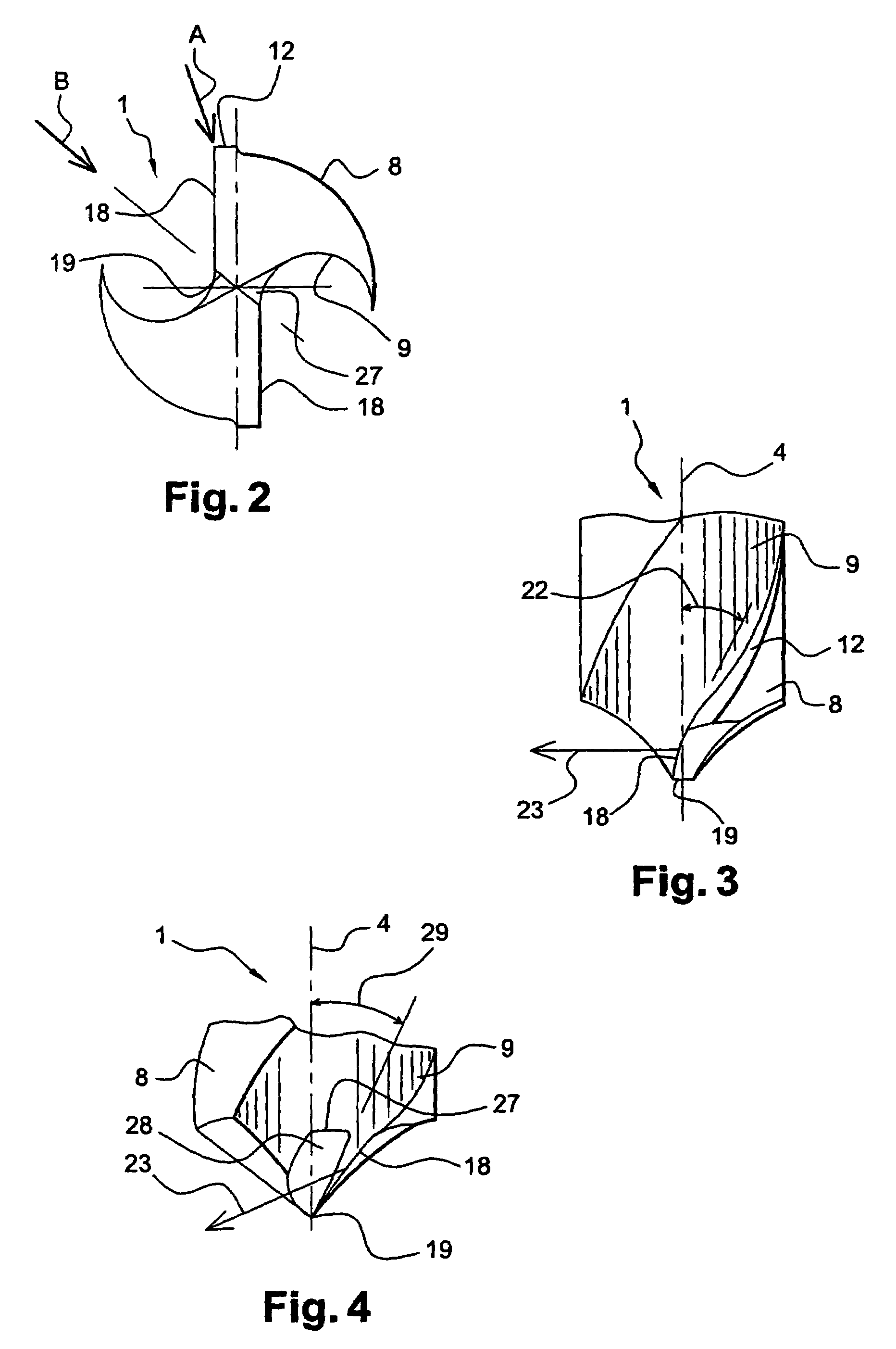
[0042]By way of example, FIGS. 1 to 4 show a one-piece ceramic drill bit for high speed drilling in materials of very great hardness, such as refractory aviation materials made of superalloys, and in particular of Inconel 718.

[0043]This ceramic bit 1 comprises (FIG. 1) a cylindrical shank 2 and a shaped portion 3 extending from the shank along the axis 4 of the bit. The shank includes an annular groove 5 for use in gripping the bit in the chuck of a machine tool (not shown). The free end 6 of the axial cylindrical shank is terminated by a chamfer 7 to facilitate inserting it into the chuck of the machine tool.

[0044]The shaped portion 3 of the bit 1 comprises two lips 8 and two flutes 9 extending in alternation around the axis 4 from the axial end 10 of the bit 1 that is remote from the shank 2, and referred to as the “tip” of the bit. The lips 8 and the flutes 9 wind helically around the axis 4 with a helix angle 11 that is less than or equal to 25°, approximately.

[0045]Each lip 8 c...


PUM

PropertyMeasurementUnit
relief angleaaaaaaaaaa
cutting anglesaaaaaaaaaa
taper angleaaaaaaaaaa

Abstract

A ceramic drill bit comprising a cylindrical shank and a shaped portion extending axially in line with the shank and having a free end forming the tip of the bit, a relief face extending from each main cutting edge with a relief angle lying in the range 4° to 10° approximately relative to a plane perpendicular to the axis of rotation of the bit, and two notches forming two secondary cutting faces extending from the central edge with positive cutting angles lying in the range 1° to 7° approximately relative to the axis of rotation of the bit.

Description

[0001]The present invention relates to a drill bit made of ceramic material. It finds a particular application in the field of aviation for very high speed drilling of very hard materials such as refractory materials, and in particular superalloys based on nickel and cobalt, e.g. Inconel 718, that are used in particular for manufacturing flanged parts for aviation applications.BACKGROUND OF THE INVENTION[0002]At present, because of their great hardness and ability to withstand high temperatures, ceramics are being used increasingly for making cutting tools. As a general rule, known ceramic cutting tools that enable high speed machining to be performed on very hard materials, such as those described in document EP-B1-0 477 093, are milling cutters and lathe tools. Unfortunately, the stresses that can be applied to a drill bit (drilling depth, swarf removal, intensity and direction of cutting forces) during a drilling operation are greater than those that might be applied, for example...

Claims


Application Information

Patent Timeline
Patent Type & Authority Patents(United States)
IPC IPC(8): B23B51/02B23B51/00
CPCB23B51/0081B23B2226/18Y10T408/03Y10T408/78Y10T408/9097
Inventor TURRINI, CLAUDEMARTINEZZERROUKI, VERONIQUE
Owner SN DETUDE & DE CONSTR DE MOTEURS DAVIATION S N E C M A
Why Eureka
Try Eureka