
Winged medical needle device

a needle device and needle-wing technology, applied in the field of medical needle devices, can solve the problems of needle-stick injuries, puncture needles, contamination and infection in medical facilities, and achieve the effect of performing safely and easily

Active Publication Date: 2008-05-06
JMS CO LTD
View PDF5 Cites 4 Cited by
  • Summary
  • Abstract
  • Description
  • Claims
  • Application Information

AI Technical Summary

Benefits of technology

The present invention relates to a winged medical needle device that includes a shield tube, a hub, and a cannula. The device has a holding mechanism that securely holds the hub in place during a puncturing action, allows for easy movement of the cannula to a storage position, and maintains the needle in a safe and secure state. The holding mechanism includes a holding mechanism at the base end of the shield tube and an inward annular protrusion that engages with the shield tube to securely hold the hub. The device also includes a bendable strip that is attached to the outer surface of the shield tube and a latching structure that allows for easy attachment and detachment of the bendable strip. The invention provides a winged medical needle device that allows for secure holding of the needle during a puncturing action, easy movement of the cannula to a storage position, and maintains the needle in a safe and secure state.

Problems solved by technology

Conventionally, contamination and infection due to needle-stick injuries from injection needles, puncture needles and the like have been a problem in medical facilities.
However, in conventional injection needle devices with a winged shield, a common mechanism is used to hold an injection needle during a puncturing action, during a storing action, and after needle storage, and thus the respective holding forces used during the puncturing action, the storing action, and after the needle storage cannot be attained suitably, which has been disadvantageous.

Method used


Image

  • Winged medical needle device
  • Winged medical needle device
  • Winged medical needle device

Examples


embodiment 1

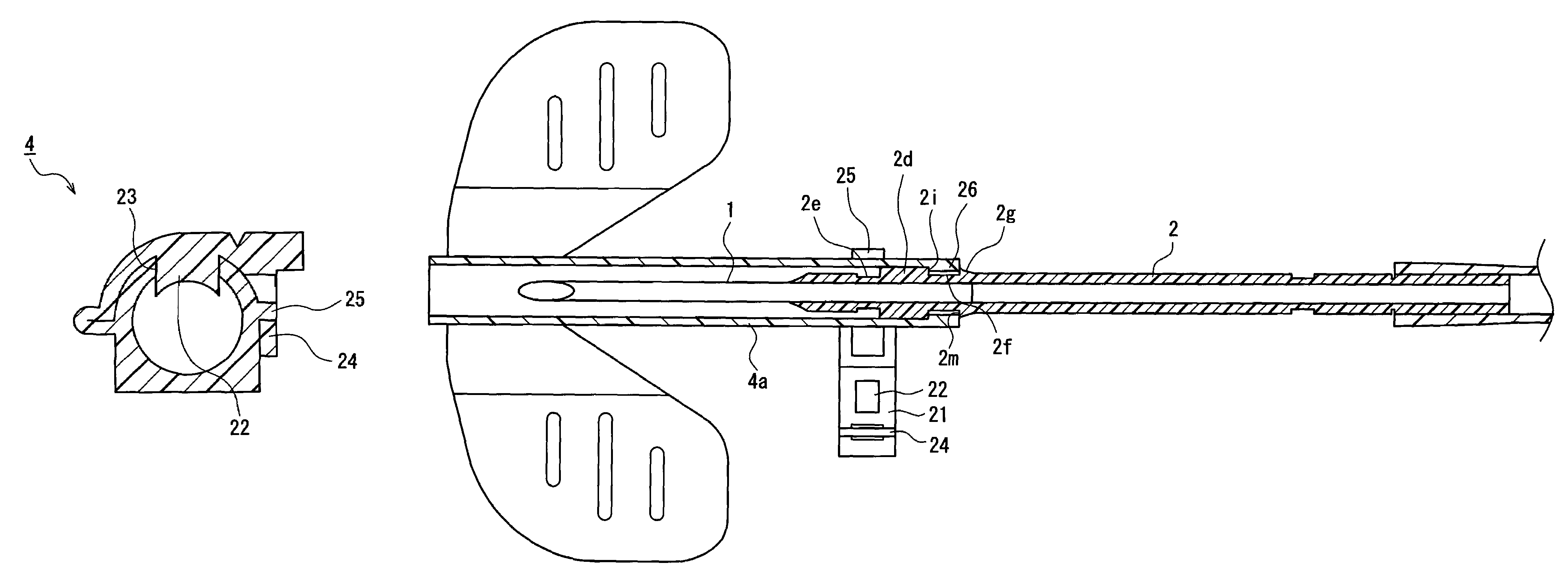
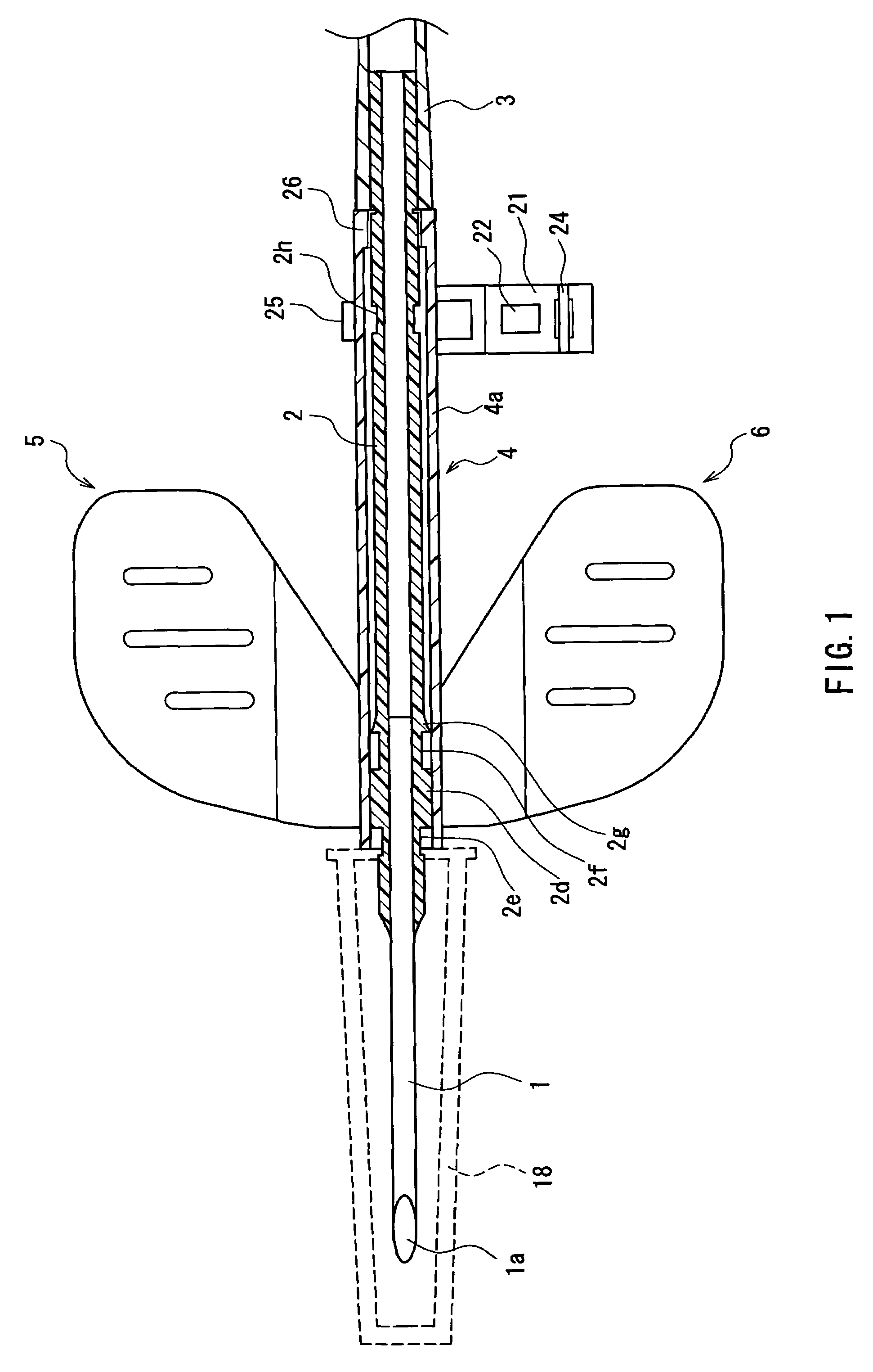
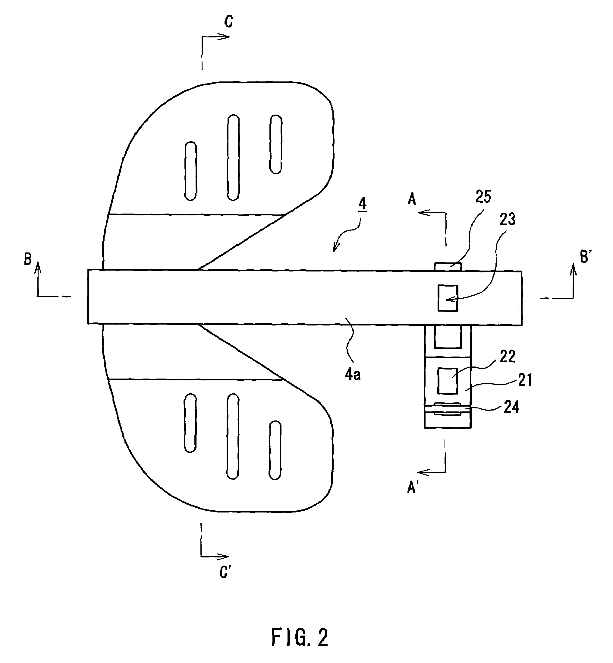
[0050]FIG. 1 is a partial cross-sectional view showing the planar shape of a winged medical needle device according to Embodiment 1 of the present invention. Numeral 1 denotes a cannula, which is fastened to the front end portion of a hub 2 made of plastic. A tube 3 is connected to the rear end portion of the hub 2. Numeral 4 denotes a winged shield, which includes a substantially cylindrical shield tube 4a made of plastic, and left and right wings 5 and 6. The hub 2 can be moved in the axial direction in the inner bore of the shield tube 4a, and the cannula 1 can be retracted into the inner bore of the shield tube 4a. The left and right wings 5 and 6 are provided at the front end portion of the shield tube 4a, i.e. at the end portion on the side from which the cannula 1 that has been retracted into the shield tube 4a protrudes. The wings 5 and 6 are linked to both sides of the peripheral surface of the shield tube 4a, and are of symmetric shape with respect to the axis of the shiel...

embodiment 2

[0084]FIG. 16 shows a shield tube of a winged medical needle device according to Embodiment 2. In the winged medical needle device according to this embodiment, in addition to the configuration of Embodiment 1, a holding tab 20 is provided at the upper surface of the shield tube 4a. As described above, after using the winged medical needle device, the tube connected to the hub is pulled toward the base end of the shield tube 4a, and the hub is held inside the shield tube 4a in the state where needle-stick injuries can be avoided. For this, the holding tab 20 is used to fasten the shield tube 4a so that it is not moved. That is, by placing a finger on the holding tab 20 and countering the force pulling the tube, the action of pulling the hub toward the base end of the shield tube 4a is facilitated. It is preferable that the holding tub 20 is formed at the front end portion of the shield tube 4a, particularly, on a side closer to the front end than the wings (see FIG. 1). With the hol...


PUM


Abstract

The configuration of the present invention includes a winged shield that has a cylindrical shield tube and wings linked to a front end side of the shield tube, a hub that is inserted into an inner bore of the shield tube so as to be movable in an axial direction, and a cannula that is mounted to a front end portion of the hub. By engaging a protrusion with a third annular groove, the hub is held with the winged shield in a state where the cannula protrudes for a predetermined length from a front end of the shield tube. In a state where an inward annular protrusion of the shield tube is engaged with a first holding portion, a tip of the cannula can be stored in the shield tube. By engaging the protrusion of a holding mechanism with a first annular groove, the hub is held with the shield tube so as not to be moved within the shield tube.

Description

BACKGROUND OF THE INVENTION[0001]1. Field of the Invention[0002]The present invention relates to a medical needle device having a winged shield for the prevention of needle-stick injuries, in which a cannula can be stored safely after use.[0003]2. Related Background Art[0004]Conventionally, contamination and infection due to needle-stick injuries from injection needles, puncture needles and the like have been a problem in medical facilities. In particular, recently, as hepatitis B, hepatitis C, HIV (human immunodeficiency virus) and the like have become a widespread social issue, there is a demand for systems that actively prevent the occurrence of accidents such as needle-stick injuries and the like.[0005]As a way to prevent needle-stick injuries, various injection needle devices that have a configuration in which a cannula is covered by a cover when injection needles or puncture needles are collected after use have been proposed. In most cases, such a system for preventing needle-...

Claims


Application Information

Patent Timeline
Patent Type & Authority Patents(United States)
IPC IPC(8): A61M5/00A61M5/32
CPCA61M25/0631A61M25/0637A61M5/3243
Inventor LIM, KAH HOCKLOW, BOON TONGYANG, CHEK LONTAO, AI LING
Owner JMS CO LTD
Learn More