
Acoustic Methods and Devices for Determining the Value of Formation Overpressure During Drilling and for Detecting Gas Packs Containing Hydrogen Sulfide Gas

a technology of hydrogen sulfide gas and overpressure, which is applied in the direction of earth-moving drilling, surveying, and well accessories, etc., can solve the problems of large damage, large damage, and modification of the buoyancy of the drilling string, and achieve high precision, safe discharge, and the effect of determining the value of formation overpressur

Inactive Publication Date: 2017-01-12
TSEYTLIN SIMON +1
View PDF1 Cites 1 Cited by
  • Summary
  • Abstract
  • Description
  • Claims
  • Application Information

AI Technical Summary

Benefits of technology

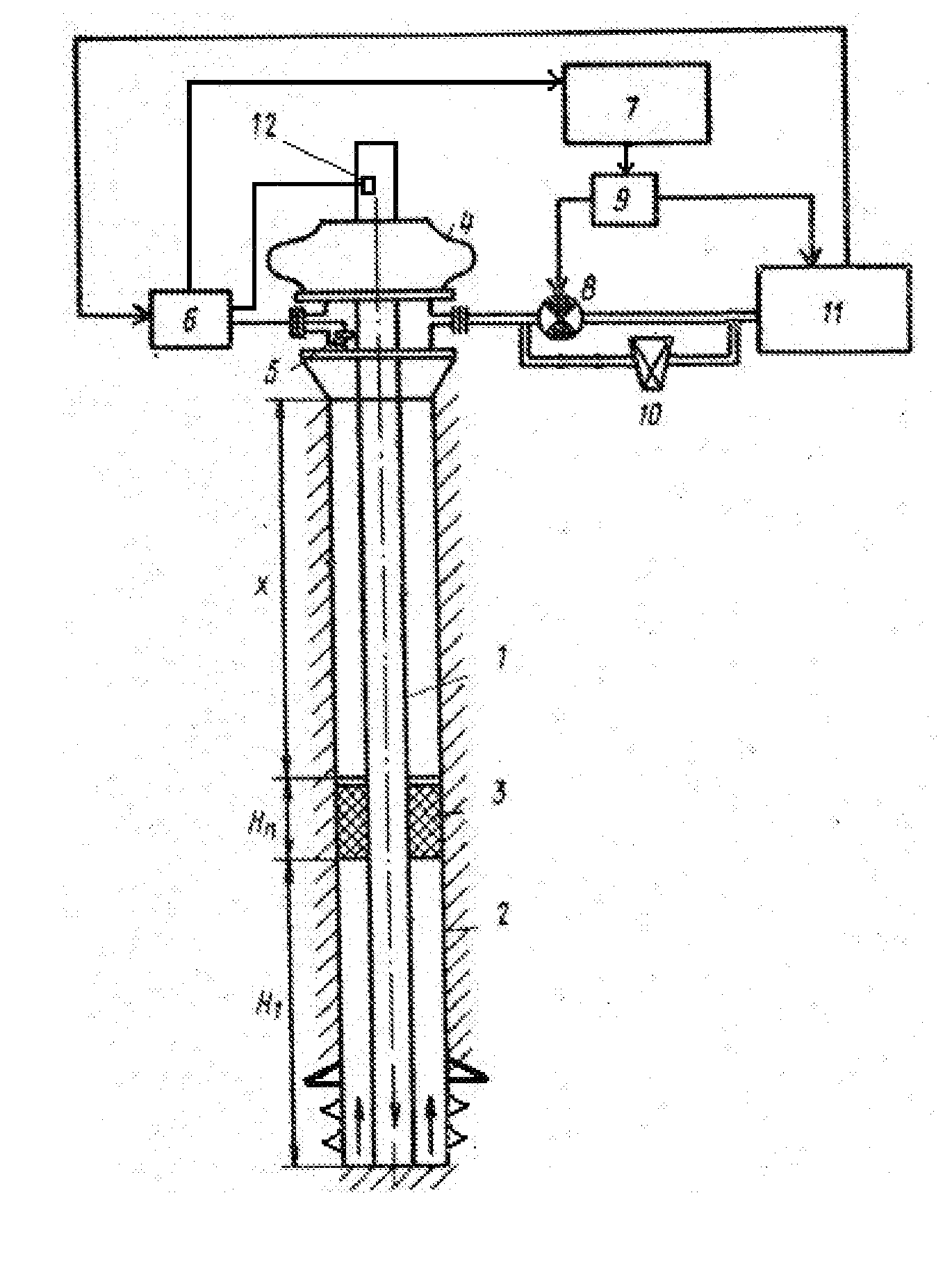
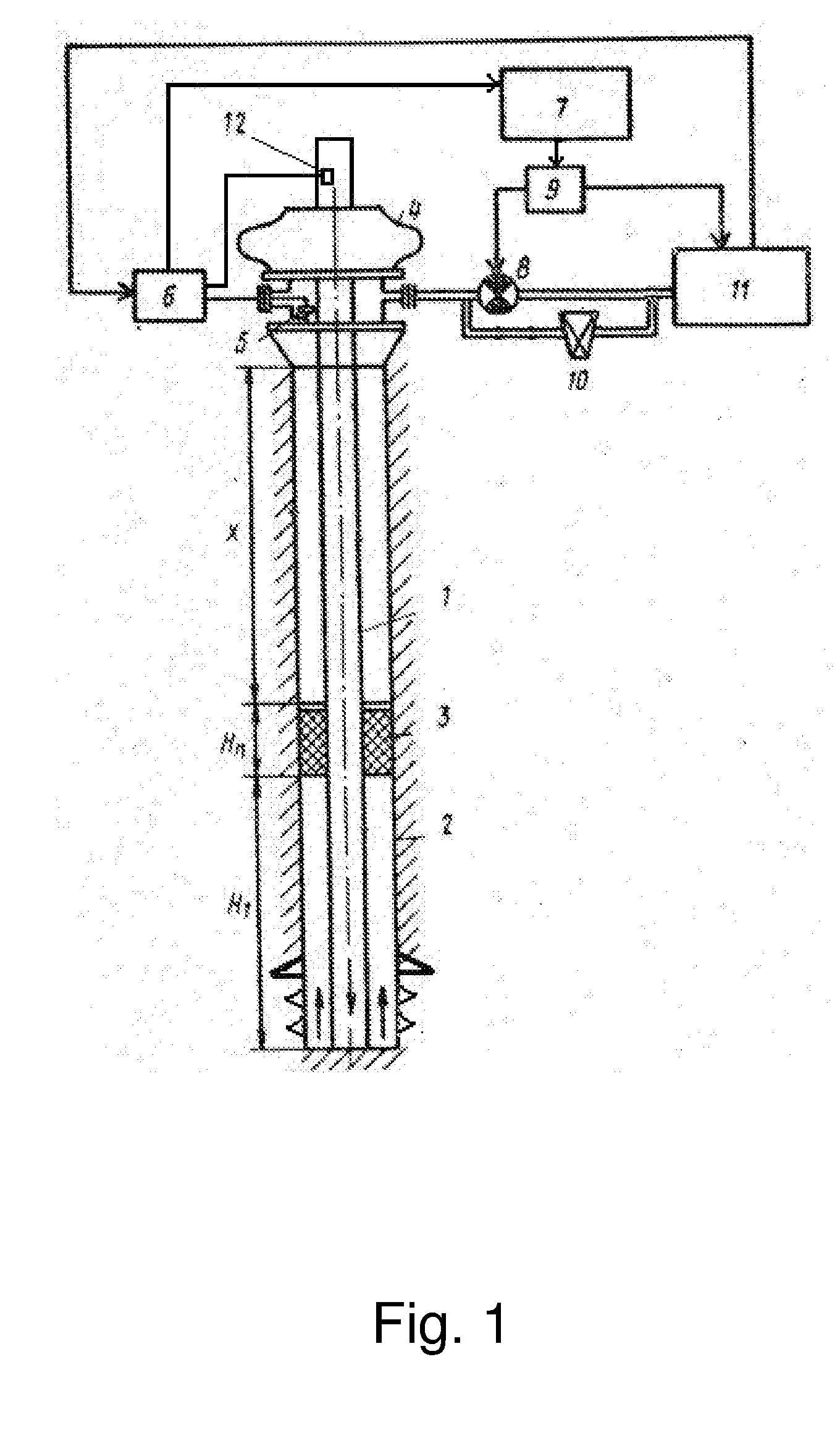
The present invention provides new methods and devices to quickly and accurately determine the formation overpressure during drilling. This helps to safely and easily discharge gas kicks and detect possible hydrogen sulfide gas kicks in advance, making oil rig personnel aware of the situation and provide more time to react appropriately. Overall, this improves the safety and efficiency of oil drilling operations.

Problems solved by technology

This gas kick may ascend to the surface, result in a modification of the buoyancy of the drilling string and can cause extensive damage if it goes undetected.
This gas is highly toxic, heavier than air, flammable and can cause substantial damage and even death to the oil well service personnel—upon inhaling such gas is extremely irritating and harmful.
Free hydrogen sulfide in the blood reduces its oxygen-carrying capacity, thereby depressing the nervous system.
Surface monitors of hydrogen sulfide presence are not sufficient to assure safety in case of hydrogen sulfide exposure.
Using high frequency positive acoustic pulses however does not allow full characterization of the gas kick as it only allows detection of its upper end and not allows detection of its lower end which is needed to detect its total volume.

Method used


Image

  • Acoustic Methods and Devices for Determining the Value of Formation Overpressure During Drilling and for Detecting Gas Packs Containing Hydrogen Sulfide Gas
  • Acoustic Methods and Devices for Determining the Value of Formation Overpressure During Drilling and for Detecting Gas Packs Containing Hydrogen Sulfide Gas
  • Acoustic Methods and Devices for Determining the Value of Formation Overpressure During Drilling and for Detecting Gas Packs Containing Hydrogen Sulfide Gas

Examples


Embodiment Construction

[0026]The following description sets forth various examples along with specific details to provide a thorough understanding of claimed subject matter. It will be understood by those skilled in the art, however, that claimed subject matter may be practiced without one or more of the specific details disclosed herein. Further, in some circumstances, well-known methods, procedures, systems, components and / or circuits have not been described in detail in order to avoid unnecessarily obscuring claimed subject matter. In the following detailed description, reference is made to the accompanying drawings, which form a part hereof. In the drawings, similar symbols typically identify similar components, unless context dictates otherwise. The illustrative embodiments described in the detailed description, drawings, and claims are not meant to be limiting. Other embodiments may be utilized, and other changes may be made, without departing from the spirit or scope of the subject matter presented...


PUM


Abstract

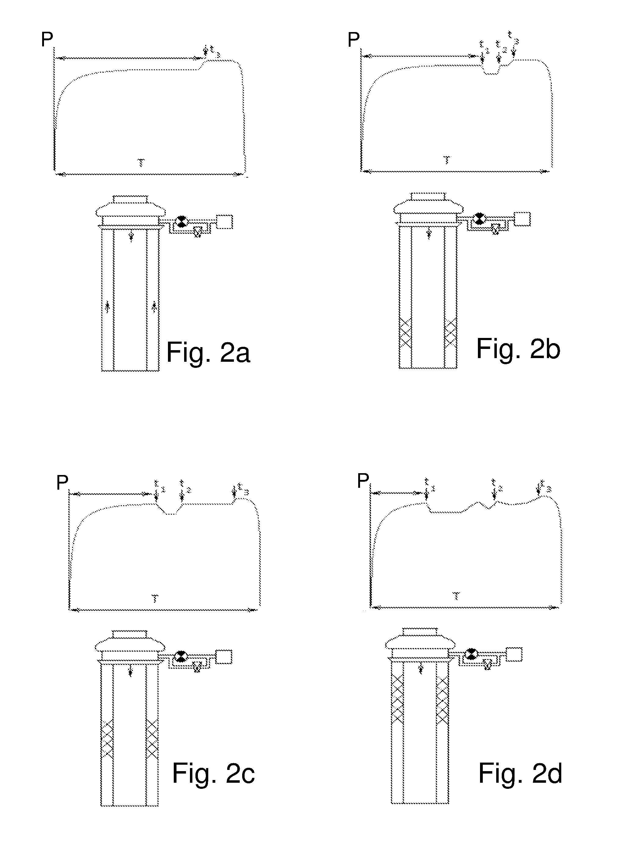
A method for determining formation pressure during exploratory drilling for oil includes generating a series of negative pressure shock waves at successively increasing well pressures to characterize gas kick forming at the bottom of a well. Once the lower end of the gas kick has been formed, the well pressure level as detected by a pressure sensor near the surface of the well is used to calculate the formation pressure along with the weight of the fluid column located in the well.

Description

CROSS-REFERENCE DATA[0001]The present patent application claims priority from a U.S. Provisional Application No. 62 / 189,157 filed 6 Jul. 2015 with the same title, which is incorporated herein in its entirety by reference.BACKGROUND OF THE INVENTION[0002]The present invention relates generally to devices and methods for exploration of oil and gas. More particularly, the invention describes how to measure formation pressure and how to detect the presence of hydrogen sulfide gas in a rising gas kick so as appropriate prevention and safety measures can be promptly taken. The present invention can be advantageously used when drilling onshore and offshore oil wells. It is designed to allow prevention of blowouts and well explosions, which usually cause human losses, damage to environment and are hard and expensive to suppress.[0003]During an exploratory drilling of an oil, gas or gas condensate wells, drilling fluid referred to in the industry as “mud”, is pumped into the drill pipe. The ...

Claims


Application Information

Patent Timeline
Patent Type & Authority Applications(United States)
IPC IPC(8): E21B21/08E21B47/06
CPCE21B47/06E21B21/08
Inventor TSEYTLIN, SIMONTSEYTLIN, DAVID
Owner TSEYTLIN SIMON
Learn More