
Traveling Route Structure Of Conveying Traveling Body

a traveling body and transportation route technology, applied in the direction of conveyor parts, railway components, transportation and packaging, etc., can solve the problems of increasing the inertia of horizontally moving the design of the horizontal rotatable guide rail part, and the increase of the inertia of the horizontal movement of the guide rail part, so as to achieve the effect of inexpensive transportation

Active Publication Date: 2015-11-26
DAIFUKU CO LTD
View PDF30 Cites 1 Cited by
  • Summary
  • Abstract
  • Description
  • Claims
  • Application Information

AI Technical Summary

Benefits of technology

The present invention provides a configuration for a traveling route that allows for easy and safe manual opening and closing of movable rails while reducing the impact and cost. The two movable rails are half the size and weight of the opening / closing area of the traveling route, which limits the impact and allows for easy maintenance. The locking means and the retracted-state locking means can be used in conjunction to prevent accidents and safely retract the movable rails. The configuration is cost-effective and reliable.

Problems solved by technology

Accordingly, the guide rail part intersecting the crossing aisle wide enough for the vehicles, etc., to pass, that is, the guide rail part designed to be horizontally rotatable, becomes very large and heavy.
Thus, even if the guide rail part is designed to be horizontally rotatable, not only are difficulties involved in manual opening and closing operation but also the inertia in horizontally moving the guide rail part is increased.

Method used


Image

  • Traveling Route Structure Of Conveying Traveling Body
  • Traveling Route Structure Of Conveying Traveling Body
  • Traveling Route Structure Of Conveying Traveling Body

Examples


Embodiment Construction

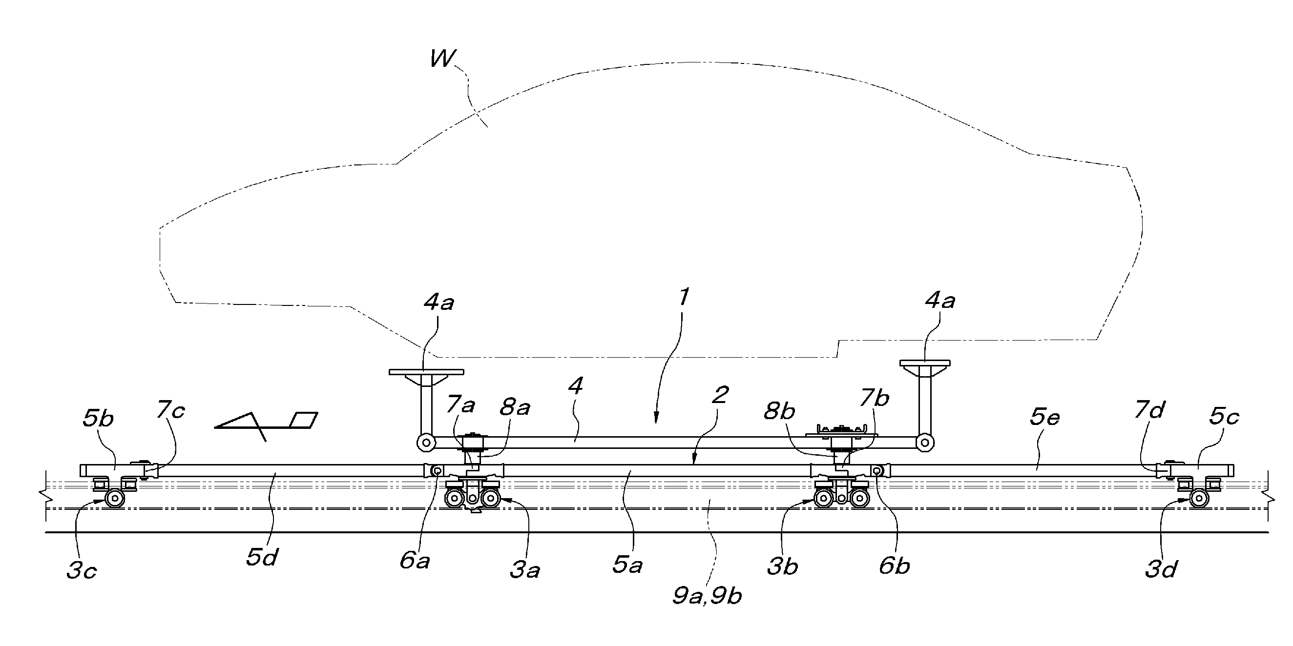
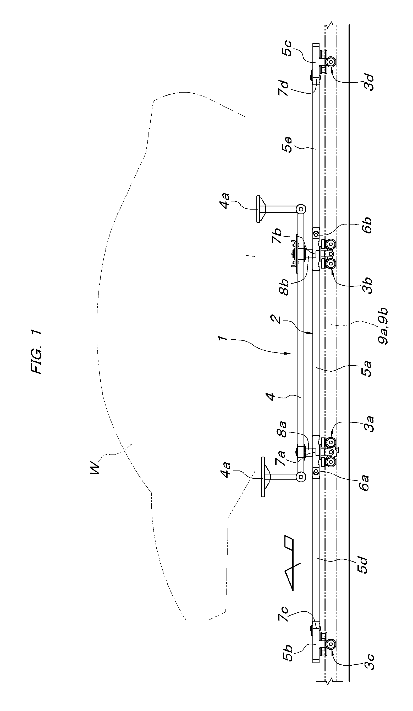
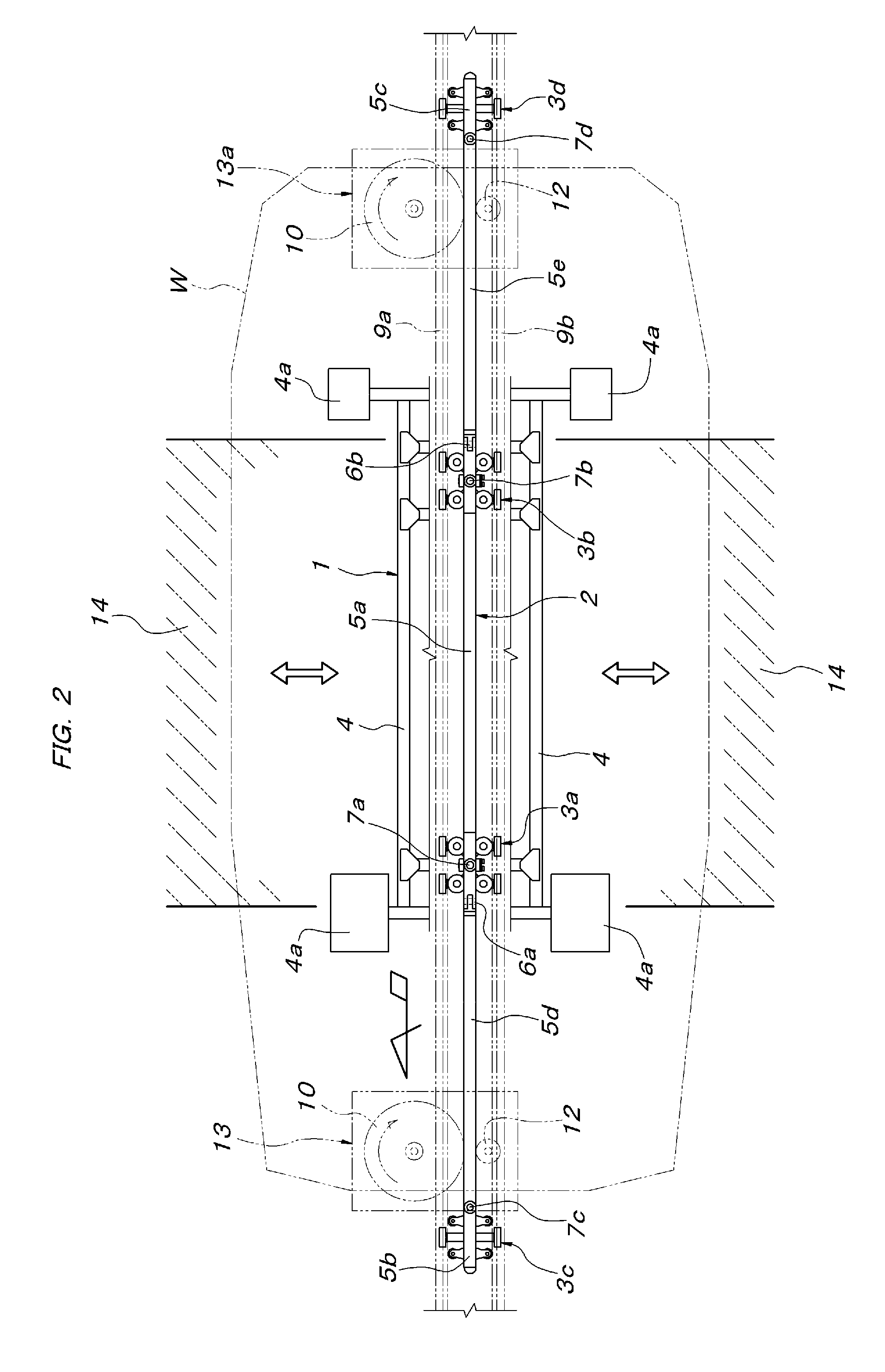
[0019]First, a configuration of a conveying traveling body used in an embodiment of the present invention will be described based on FIGS. 1 to 3. The conveying traveling body 1 is composed of a load bar 2 longer than the entire length of a conveyed object W, a plurality of trolleys 3a to 3d supporting the load bar 2, and a carriage main body 4 supported by a pair of front and rear load trolleys 3a, 3b at intermediate positions of the trolleys. The load bar 2 is composed of a central load bar unit 5a located between the pair of front and rear load trolleys 3a, 3b, front- and rear-end load bar units 5b, 5c integrated with guide trolleys 3c, 3d at both front and rear ends, and a front and a rear intermediate load bar unit 5d, 5e coupling the front- and rear-end load bar units 5b, 5c and the central load bar unit 5a. To allow the conveying traveling body 1 to travel on a horizontal curved route portion and a rising and falling gradient route portion, vertical swing joint portions 6a, 6...


PUM


Abstract

A traveling route structure of a conveying traveling body has a traveling route with an area intersecting a crossing aisle, and has a movable rail horizontally openable and closable between a connection working position that connects guide rails in front and rear of the crossing aisle and a retracting position lateral to the crossing aisle. The movable rail has front and a rear movable rails arranged in a line when the movable rails are in the connection working position. Each of the movable rails is pivotally supported so as to be horizontally rotatable about a vertical spindle at each outer end portion positioned outside of the crossing aisle. A locking means couples inner end portions of both movable rails together, with the inner end portions being adjacent to each other when the movable rails are in the connection working position.

Description

FIELD OF THE INVENTION[0001]The present invention relates to a traveling route structure of a conveying traveling body, provided with a traveling route so as to intersect an aisle on the floor.BACKGROUND OF THE INVENTION[0002]It is known, where a crossing aisle crossing the traveling route of the conveying traveling body is provided on the floor, that elevating guide rails constituting a traveling route part intersecting the crossing aisle are designed to be able to be lowered and retracted into a pit provided under the floor and when the crossing aisle is used for the passage of vehicles, etc., the elevating guide rails are lowered and retracted into the pit such that the vehicles, etc., can pass on the lowered and retracted elevating guide rails, as described in Patent Document 1 (Japanese unexamined patent application publication No. 2008-238914). This configuration is very costly because a pit is needed under the floor, an upper end surface of the elevating guide rail needs to b...

Claims


Application Information

Patent Timeline
IPC IPC(8): B61J1/00
CPCB61J1/00B61B13/125B65G49/0445
Inventor NAKAMURA, JIRO
Owner DAIFUKU CO LTD
Learn More