Tracking system for lightweight solar collector assembly and array

Inactive Publication Date: 2013-09-03
THE UNITED STATES OF AMERICA AS REPRESENTED BY THE SECRETARY OF THE NAVY
View PDF47 Cites 5 Cited by
  • Summary
  • Abstract
  • Description
  • Claims
  • Application Information

AI Technical Summary

Benefits of technology

[0011]Accordingly, a primary object of this invention is to provide a solar energy concentrator which substantially overcomes or avoids a number of the aforesaid problems encountered in the manufacture and use of solar energy collector systems according to prior art. Another object is to provide a method of making solar energy concentrators which are especially light weight, and which can be manufactured using relatively inexpensive, commercially available materials. Yet other objects of the invention are (1) to provide solar energy concentrators which may be effectively and easily employed for the collec

Problems solved by technology

While many of these systems are quite efficient in accomplishing the objective, i.e. collecting and storing solar energy to supplement or replace more expensive systems utilizing common sources of energy, one primary problem remains, the initial cost of making and installing an efficient solar energy collecting system.
If a solar energy collecting system is very expensive to make and install, such high capital expenditure is undesirable, since the potential user must wait too long to amortize this cost before realizing any savings in energy expense.
At the current state of the art, a principal obstacle to wide scale adoption of solar cell energy collector installations is that manufacturing and installation costs of solar cell arrays generally are substantia

Method used


Image

  • Tracking system for lightweight solar collector assembly and array
  • Tracking system for lightweight solar collector assembly and array
  • Tracking system for lightweight solar collector assembly and array

Examples


Embodiment Construction

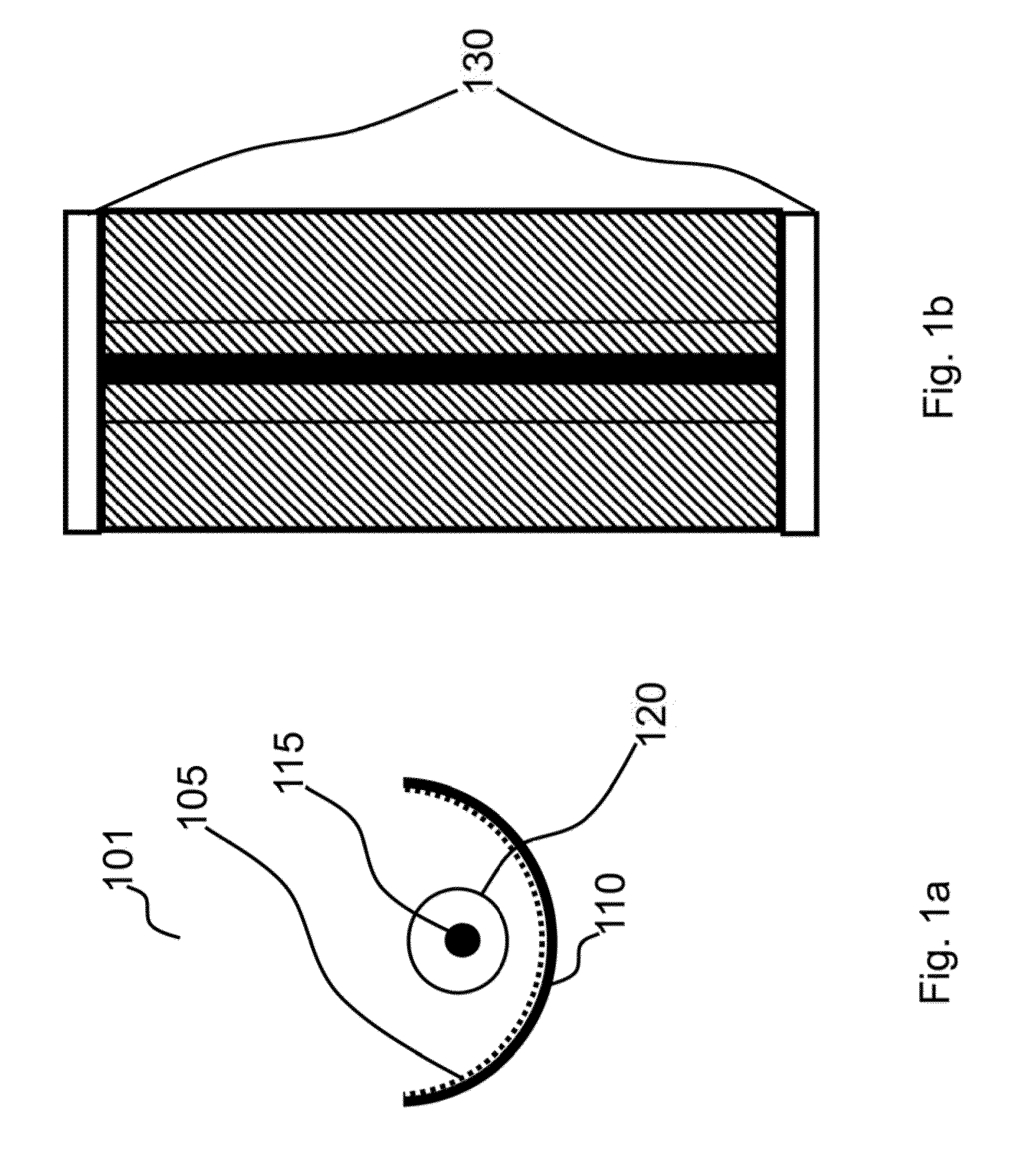
[0051]FIG. 1a is an end view of a solar energy collector 101 utilizing the lightweight aperture of the invention. FIG. 1b is a top view of the solar energy collector 101 of FIG. 1a, and can be either a complete collector or section of a longer collector. Solar energy collector 101 is an example of a concentrator. Solar energy collector 101 comprises a reflector 105 with a concentrating shape, which in this case is approximately the shape of a parabolic trough. The parabolic trough shape is a specific example of an approximately constant cross-section shape. The parabolic trough shape is a specific example of a surface with substantial curvature in only one dimension. Reflector 105 is held in place and in shape by trough 110 which is an example of a first support means for the reflector 105. By itself, reflector 105 would not be able to maintain its shape against the force of gravity since it is very thin and hence very flexible. A preferred example of reflector 105 is a metallized (...


PUM


Abstract

A tracking system for a solar collector assembly array where the tracking system includes a coplanar circular rim structure including multiple circular rims, where each circular rim is fitted around a respective solar collector and where each solar collector has a general shape of a sealed and inflated cylindrical tube housing having a longitudinal center axis and where each solar collector is in a horizontal planar array with respect to each other. The tracking system further includes a first elongated frame structure for supporting the circular rim structure such that all of the circular rims are generally vertically coplanar with one another. The tracking system further includes a cable serially wrapped around each of the respective circular rims to form a closed cable loop where the wrapped cable forms a series of a generally vertical coplanar loops with each loop contacting around a respective rim structure such that at least one generally complete gripping loop is formed on each respective rim. An actuator is attached to the frame structure such that actuator provides a controllable driving force to the closed cable loop to allow for controlled rotation of each solar collector assembly around its respective longitudinal axis.

Description

FEDERALLY-SPONSORED RESEARCH AND DEVELOPMENT[0001]This invention (Navy Case NC 100,711) is assigned to the United States Government and is available for licensing for commercial purposes. Licensing and technical inquiries may be directed to the Office of Research and Technical Applications, Space and Naval Warfare Systems Center, Pacific, Code 72120, San Diego, Calif., 92152; voice (619) 553-5118; email ssc_pac_t2@navy.milCROSS-REFERENCE TO RELATED PATENT APPLICATIONS[0002]This application is related to application Ser. No. 13 / 017,154, filed Jan. 31, 2011, entitled “Lightweight Solar Collector Assembly and Array”, which is assigned to the same assignee as the present application and which is hereby incorporated by reference herein.BACKGROUND OF THE INVENTION[0003]This invention relates generally to apertures of radiant energy (e.g. electromagnetic radiation and sound) both for collecting and emitting. The aperture of the invention is particularly adaptable to the collection of solar...

Claims


Application Information

Patent Timeline
IPC IPC(8): F24J2/38F24S50/20
CPCF24J2/125F24J2/5403F24J2/055Y02E10/47Y02E10/44Y02E10/42F24J2002/5482F24J2002/5458F24S10/45F24S23/715F24S30/42F24S2030/133F24S2030/15Y02E10/40
Inventor OLSEN, RANDALL B.
Owner THE UNITED STATES OF AMERICA AS REPRESENTED BY THE SECRETARY OF THE NAVY
Why Eureka
Try Eureka