Method for operating a vehicle drive train

a technology for driving trains and vehicles, applied in mechanical equipment, multiple ratio transmissions, transportation and packaging, etc., can solve the problems of undesired damage to the overall efficiency of automatic transmissions, undesirable increase in the manufacturing cost of transmission devices and the structural space occupied, and achieve the effect of occupying a small structural spa

Active Publication Date: 2011-10-27
ZF FRIEDRICHSHAFEN AG
View PDF5 Cites 5 Cited by
  • Summary
  • Abstract
  • Description
  • Claims
  • Application Information

AI Technical Summary

Benefits of technology

[0009]Accordingly, the purpose of the present invention is to make available a method for operating vehicle drive trains, by means of which shift operations in the transmission devices, in particular automatic transmissions, which involve at least one interlocking shift element can be carried out within acceptable shifting times, inexpensively, and with little structural space occupation particularly in the area of the transmission device.

Problems solved by technology

Disadvantageously, frictional shift elements in the disengaged operating condition give rise to drag torques which impair the overall efficiency of an automatic transmission to an undesired extent.
Furthermore, interlocking shift elements engaged in the force flow of a transmission device can only be disengaged from the force flow with small shifting forces provided that they are close to their load-free operating condition.
Such additional structural devices, however, undesirably increase both the manufacturing costs of a transmission device and the structural space that it occupies.

Method used


Image

  • Method for operating a vehicle drive train
  • Method for operating a vehicle drive train
  • Method for operating a vehicle drive train

Examples


Embodiment Construction

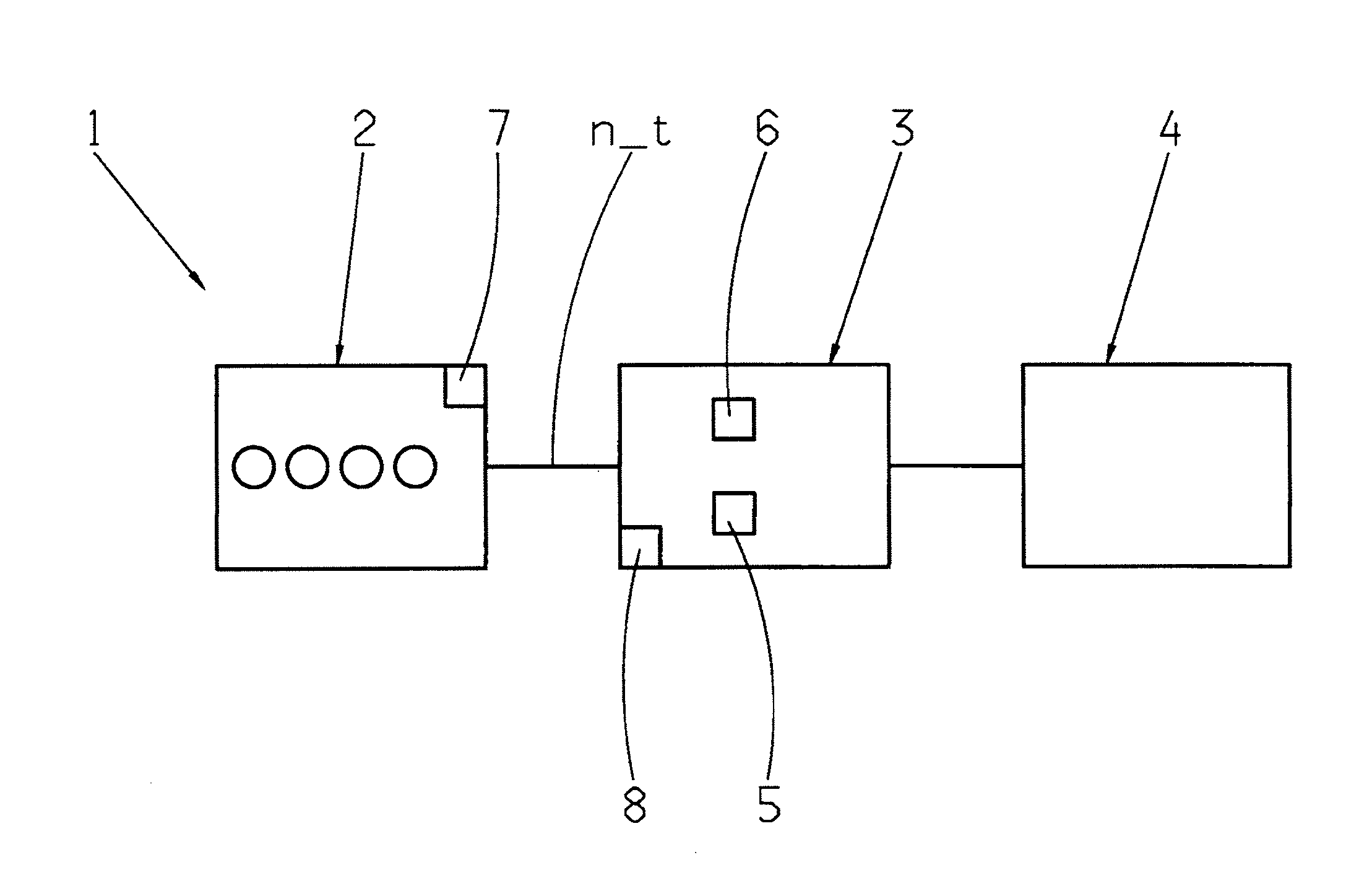
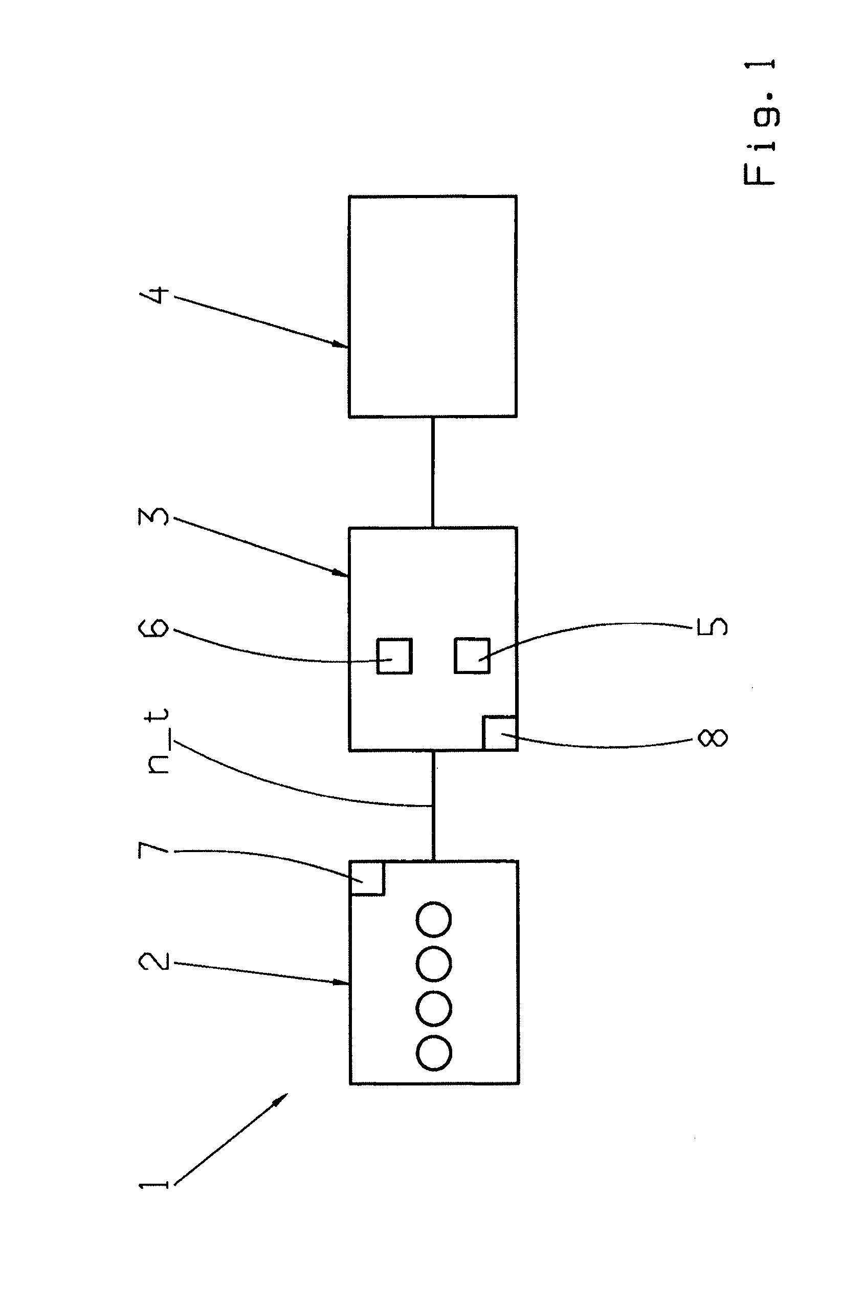
[0022]FIG. 1 shows a vehicle drive train 1 with a drive machine 2 in this case in the form of an internal combustion engine, a transmission device 3 and a drive output 4, the transmission device being an automatic transmission. The transmission device 3 is constructed with a plurality of frictional shift elements 5 and at least one interlocking shift element 6, in order to be able to obtain various gear ratios for forward and reverse driving as a function of its operating condition and as a function of shift commands.

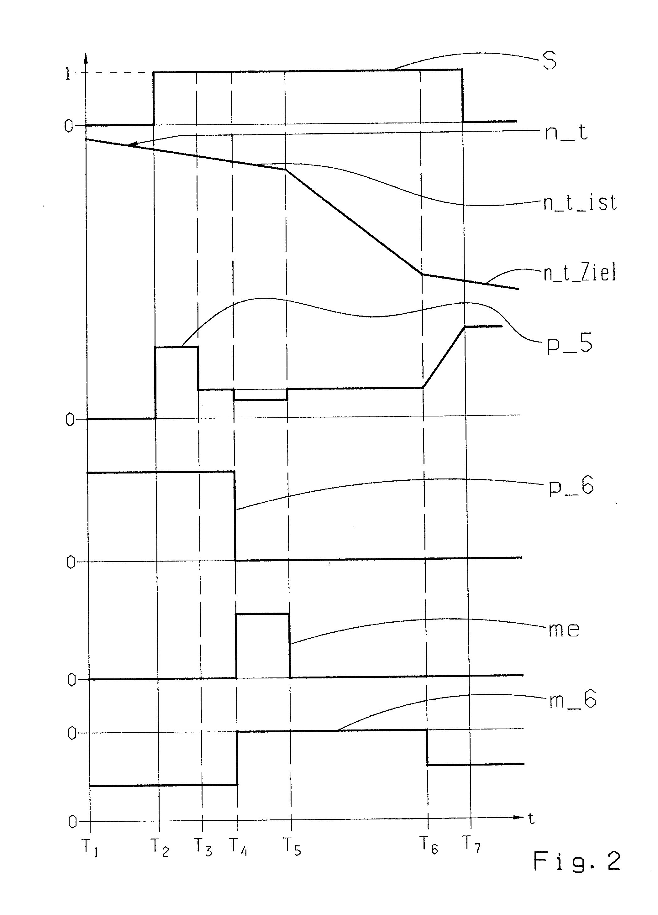
[0023]When a shift command is given for a gear ratio change in the transmission device 3 or to carry out a coasting upshift, during which an interlocking shift element 6 engaged in the force flow to produce the gear ratio currently engaged in the transmission device 3 has to be disengaged, whereas at least one of the frictional shift elements 5 has to be engaged in the force flow of the transmission device 3, the method described in more detail below with reference to t...


PUM


Abstract

A method is described for operating a vehicle drive train (1) with a drive machine (2) and with a transmission device (3) during a coast upshift, during which at least one interlocking shift element (6) that is engaged in the force flow of the transmission device (3) to produce the gear ratio to be disengaged is disengaged from the force flow and also frictional shift element (5) that has to be engaged in the force flow of the transmission device (3) to obtain the gear ratio to be engaged is engaged in the force flow. According to the invention, when a shift command is given for a gear ratio change, a torque applied at the interlocking shift element (6) to be disengaged is reduced at least approximately to zero by a defined engine intervention and the interlocking shift element (6) is then disengaged from the force flow of the transmission device (3).

Description

[0001]This application is a National Stage completion of PCT / EP2010 / 050340 filed Jan. 13, 2010, which claims priority from German patent application serial no. 10 2009 000 252.9 filed Jan. 15, 2009.FIELD OF THE INVENTION[0002]The invention concerns a method for operating a vehicle drive train.BACKGROUND OF THE INVENTION[0003]Vehicle drive trains known from practice are to an increasing extent constructed with automatic transmissions having frictional shift elements such as disk clutches or disk brakes. When a command is given for a gear ratio change in the automatic transmission, at least one frictional shift element engaged in the force flow of the automatic transmission in order to produce the gear ratio currently engaged in the automatic transmission has to be disengaged from the force flow of the automatic transmission, and at least one other frictional shift element, which is disengaged from the force flow of the automatic transmission while the current gear ratio is engaged, h...

Claims


Application Information

Patent Timeline
Patent Type & Authority Applications(United States)
IPC IPC(8): B60W10/10B60W30/00B60W10/04
CPCF16H61/0437F16H63/502F16H2306/42F16H2306/46F16H2306/44Y10T477/78F16H2059/186F16H2200/2094Y10T477/68Y10T477/675F16H2200/2064F16H61/04F16H63/50
Inventor CUPPERS, RUBENHERBETH, VALENTINE
Owner ZF FRIEDRICHSHAFEN AG
Why Eureka
Try Eureka