
Device for non-destructive testing of a structure by vibratory analysis

a technology of non-destructive testing and vibratory analysis, which is applied in the direction of structural/machine measurement, vibration measurement in solids, instruments, etc., can solve the problems of difficult application, unsuitable for use on aircraft structures, and structural defects, so as to reduce the work of operators and reduce the cost of maintenance

Inactive Publication Date: 2012-04-10
AIRBUS OPERATIONS (SAS)
View PDF28 Cites 6 Cited by
  • Summary
  • Abstract
  • Description
  • Claims
  • Application Information

AI Technical Summary

Benefits of technology

[0014]to provide a means of testing suitable for permanent installation on the structures to be tested during their use, so as to conduct predictive maintenance by detecting the appearance of defects as soon as possible, thereby enabling work to be scheduled and repairs to be carried out more cheaply, and ensuring maximum structural safety;
[0015]to provide a means of testing that enables automatic management of the inspections and that provides a full analysis of the structures' health, so as to reduce the operator's work as much as possible in order to reduce the cost of maintenance.

Problems solved by technology

In some cases these vibrations are indicators of the appearance of defects in the structures, e.g., the development of fissures or cracks in the material constituting the aircraft's structure.
For example, there are means of testing by using x-ray radiography or magnetic induction that can detect defects in a structure, but these means are difficult to apply, and unsuitable for use on an aircraft structure unless the aircraft is stationary.
There are also visual testing means for detecting the appearance of fissures, but in general the structures in which defects are most likely to develop are structures that present access difficulties, such as fastenings or complex moving structures.
These means enable the detection of fissures only when the fissures emerge on a surface directly accessible to the operator, thus visual testing means do not provide for effective predictive maintenance of the structures.
This entails a relatively long testing period and the presence of a qualified operator, thereby leading to a relatively high maintenance cost.
As far as the designer of this device knows, there is currently no effective means for inspecting the status of structures, e.g., aeronautical structures, throughout their periods of use, and in particular for carrying out an overall evaluation of the health of aeronautical structures while the airplane is in flight.

Method used


Image

  • Device for non-destructive testing of a structure by vibratory analysis
  • Device for non-destructive testing of a structure by vibratory analysis
  • Device for non-destructive testing of a structure by vibratory analysis

Examples


Embodiment Construction

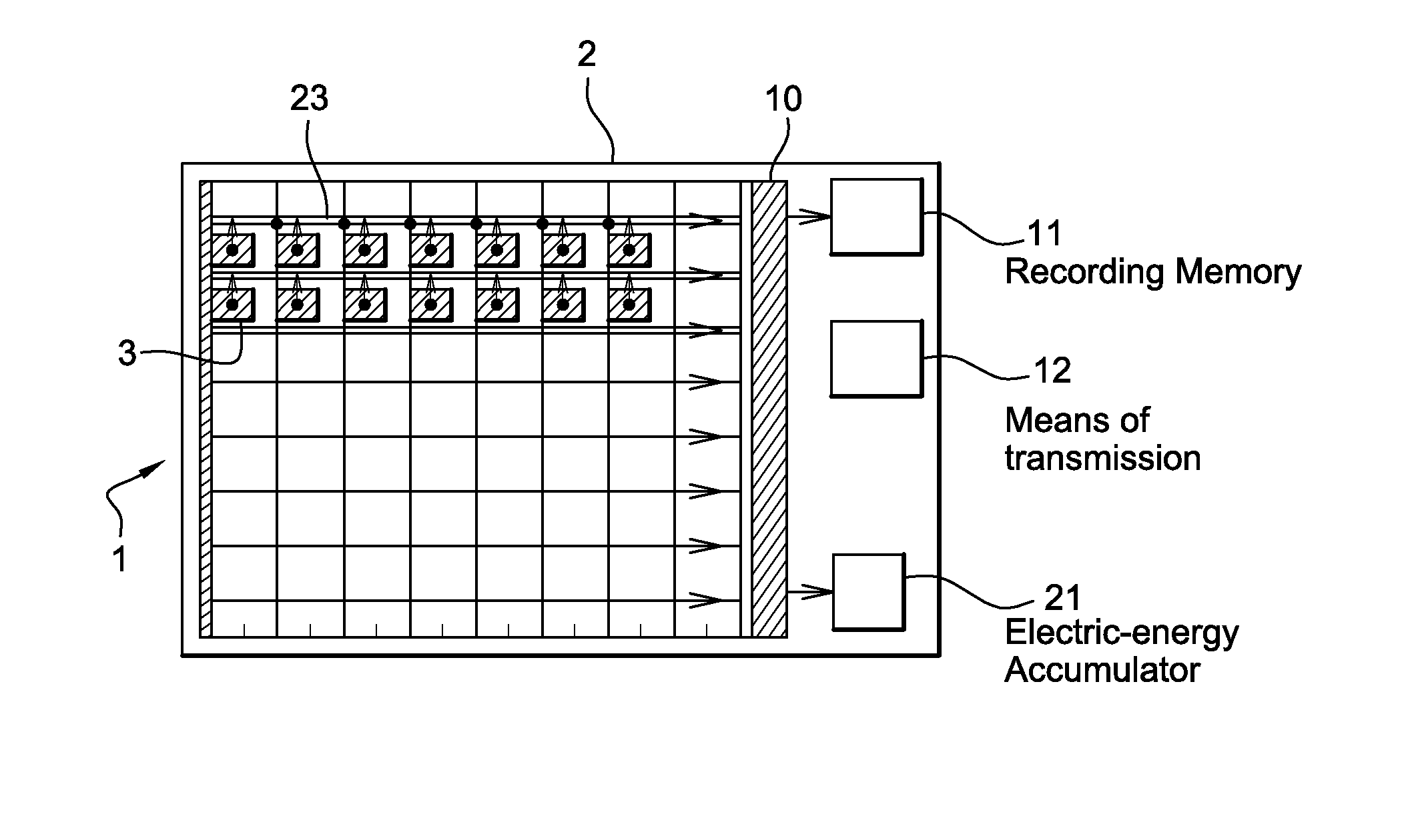
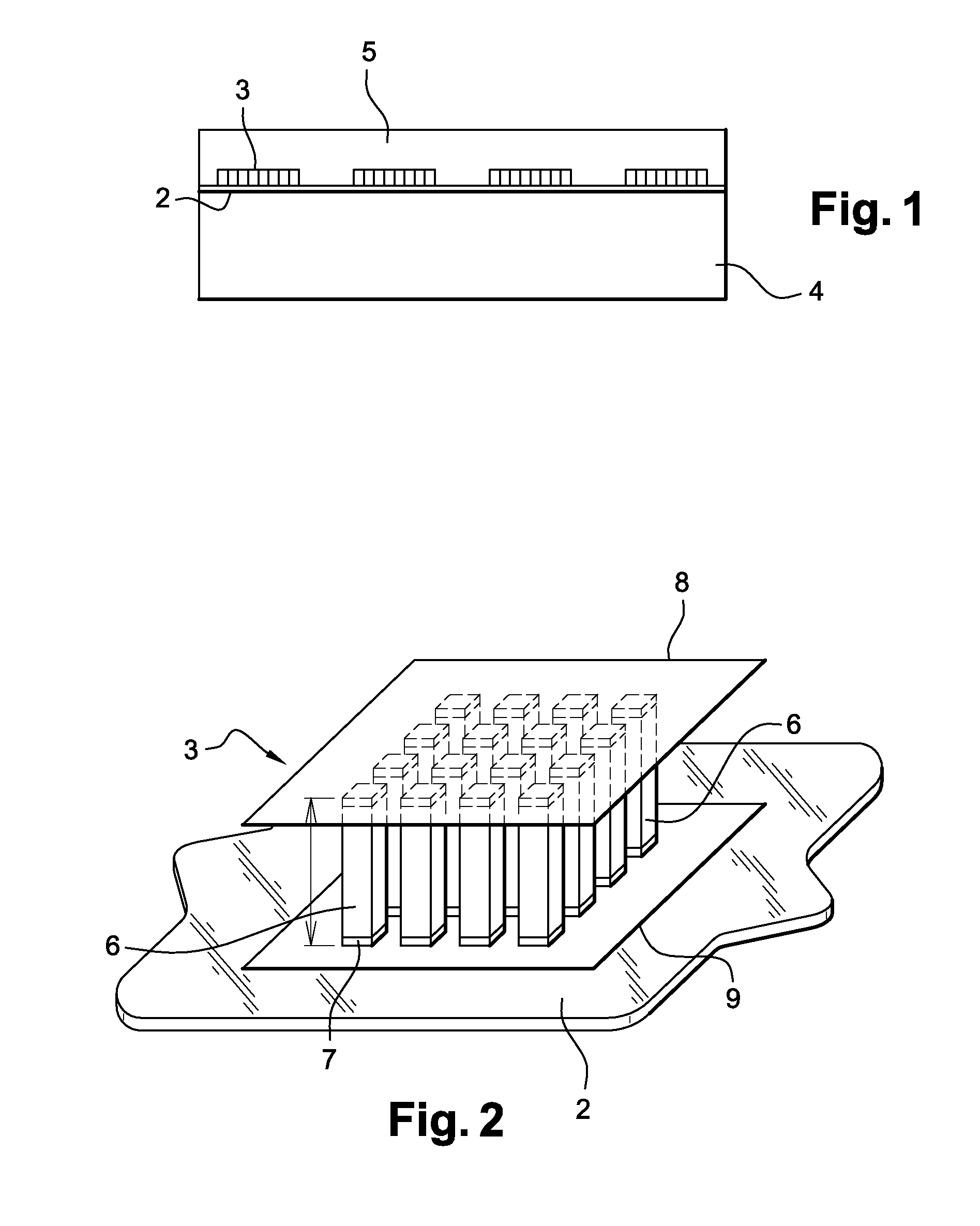
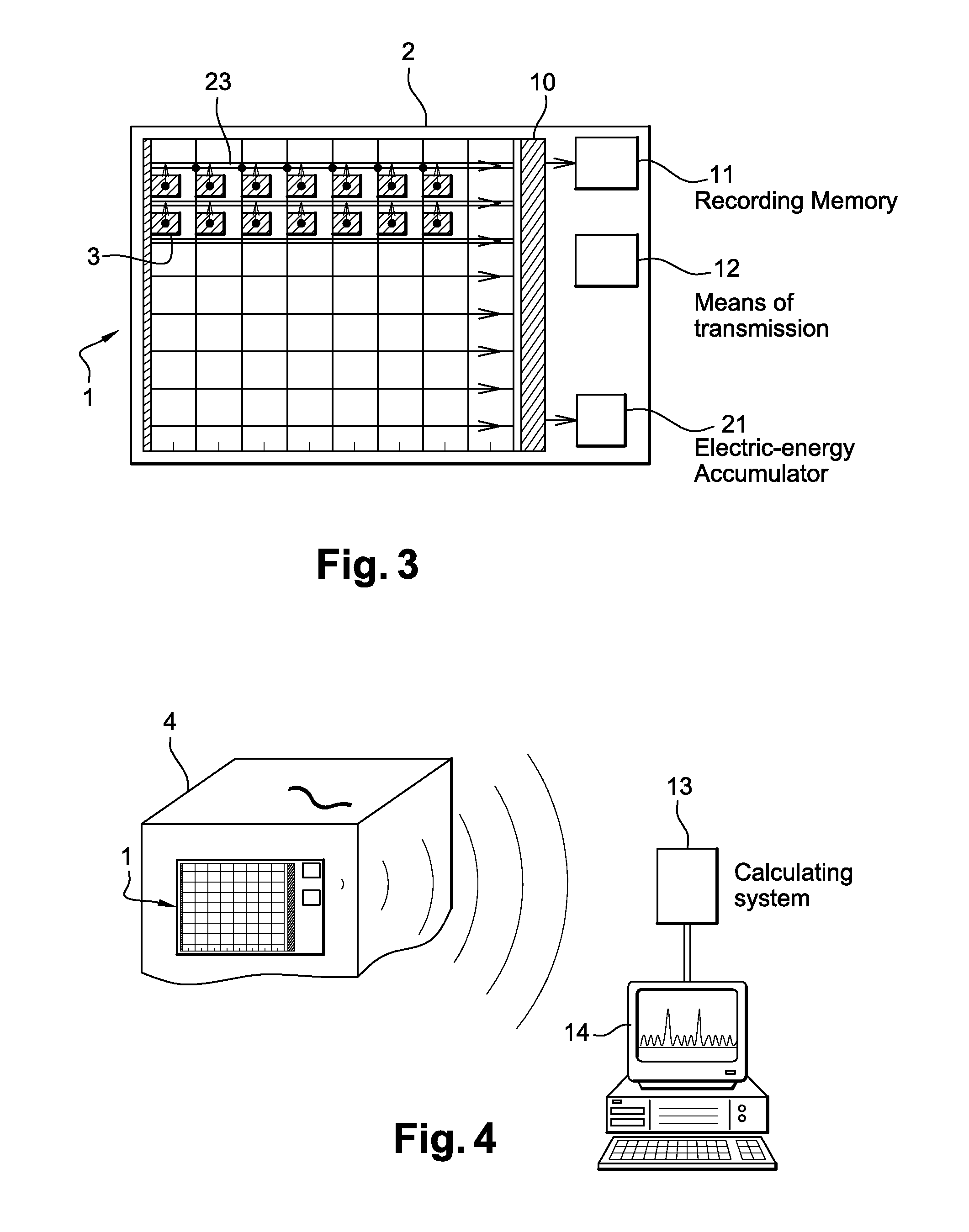
[0041]FIG. 1 shows a non-destructive testing device 1 on a structure 4 according to the disclosed embodiments, for detecting and measuring the vibratory waves caused by the presence of a defect in a structure.

[0042]It comprises a flexible housing 2 into which are incorporated the means of measuring 3 for vibratory waves emitted by said structure at various points on the surface of the structure. The flexible housing 2 may for example be made of a plastic material allowing the device to be attached to the surface of the structure to be tested, by following the shape of the structure.

[0043]The flexible housing of the testing device 1 is fixed to the surface of the structure 4 to be tested by means of an adhesive material.

[0044]This device should preferably be attached to a critical area of the structure where cracks are liable to appear. On an aircraft, the device may be placed on areas regarded as critical, located for example where the ailerons are coupled on, in areas where fuselag...


PUM


Abstract

A device for non-destructive testing of a structure likely to contain a defect, including microsensors for measuring vibratory waves emitted by the structure at different points of a surface of the structure, the aforementioned microsensors being integrated in a flexible housing capable of adhering on the surface of the structure to be tested. The disclosed embodiments are applicable to all industrial sectors where testing of the integrity of structures is important, in particular in areonautics.

Description

CROSS REFERENCE TO RELATED APPLICATIONS[0001]This application is the National Stage of International Application No. PCT / EP2007 / 054759 International Filing Date, 16 May 2007, which designated the United States of America, and which International Application was published under PCT Article 21 (2) as WO Publication No. WO2007 / 135057 and which claims priority from French Application No. 0651903, filed on 24 May 2006, the disclosures of which are incorporated herein by reference in their entireties.[0002]This application is also related to U.S. patent application Ser. No. 12 / 301,646, filed on Jun. 23, 2009, (International Application Serial No. PCT / EP2007 / 054762) and U.S. patent application Ser. No. 12,301,701, filed on Jun. 23, 2009, (International Application Serial No. PCT / EP2007 / 054751) the disclosures of which are incorporated herein by reference in their entireties.BACKGROUND[0003]1. Field[0004]The disclosed embodiments concern a device for non-destructive testing of a structure b...

Claims


Application Information

Patent Timeline
IPC IPC(8): G01N29/14G01M99/00H10N30/88
CPCG01H11/08G01M5/0033G01N29/14G01N29/223G01M5/0066G01N2291/2694
Inventor DE SMET, MARIE-ANNE
Owner AIRBUS OPERATIONS (SAS)
Learn More