Electrically shielded module carrier

a module carrier and shielding technology, applied in the direction of electrical apparatus casings/cabinets/drawers, rack/frame construction, support structure mounting, etc., can solve the problems of requiring corresponding expenditure, increasing integration and component density, and comparatively high production costs of the module frame, so as to achieve low cost and large production. economic

Inactive Publication Date: 2008-05-06
UNIFY GMBH & CO KG
View PDF16 Cites 22 Cited by
  • Summary
  • Abstract
  • Description
  • Claims
  • Application Information

AI Technical Summary

Benefits of technology

[0014]An aspect of the invention is to create a module carrier at low cost, with which the mounting space for electronic modules is reliably shielded from electromagnetic parasitic radiation and which can be produced economically in large numbers.

Problems solved by technology

In many areas of electrical engineering, in particular in the area of communication technology, the problem arises that in the module carrier the mounting space for electronic units has to be protected against parasitic radiation, while electric components, such as fans, power supply units and cabling, also have to be housed in module carriers.
Such all-round contact, which can be achieved by spot welding, screws, rivets, screened springs, contact lugs or flexible sheathed electric cables, requires corresponding expenditure.
A further problem results from the demand for increasing integration and component density.
Production of the module frame is comparatively expensive, as the backplane carrier represents an additional component with additional production costs.

Method used


Image

  • Electrically shielded module carrier
  • Electrically shielded module carrier
  • Electrically shielded module carrier

Examples


Embodiment Construction

[0034]Reference will now be made in detail to the preferred embodiments of the present invention, examples of which are illustrated in the accompanying drawings, wherein like reference numerals refer to like elements throughout.

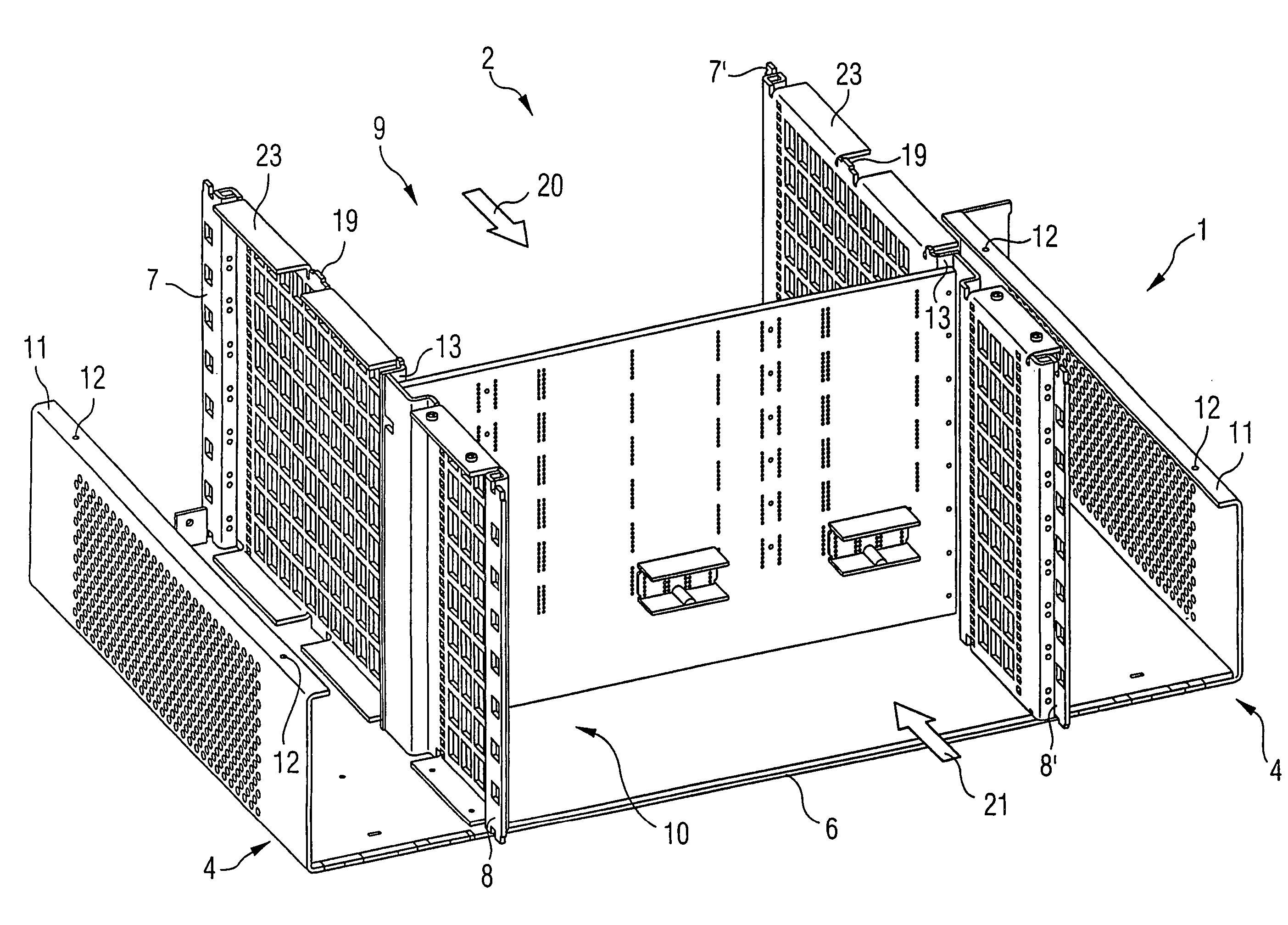
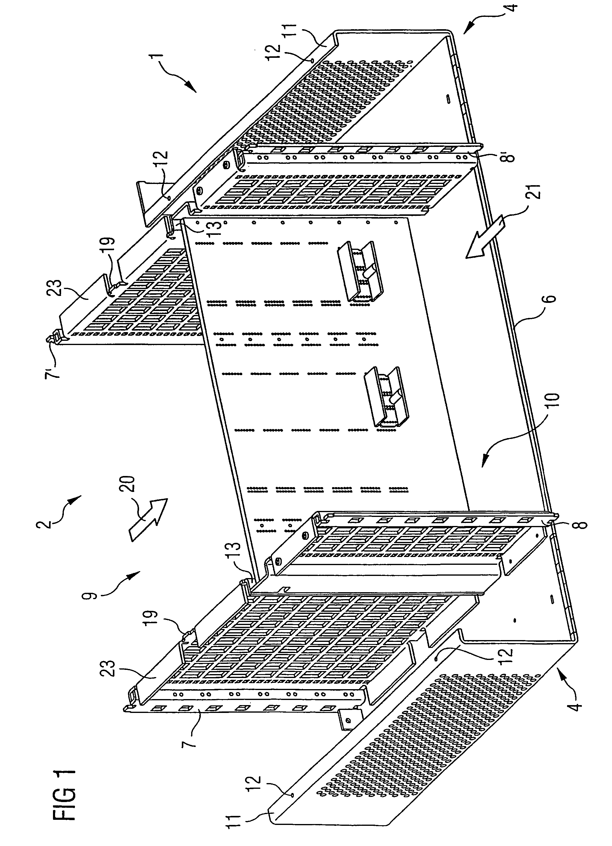
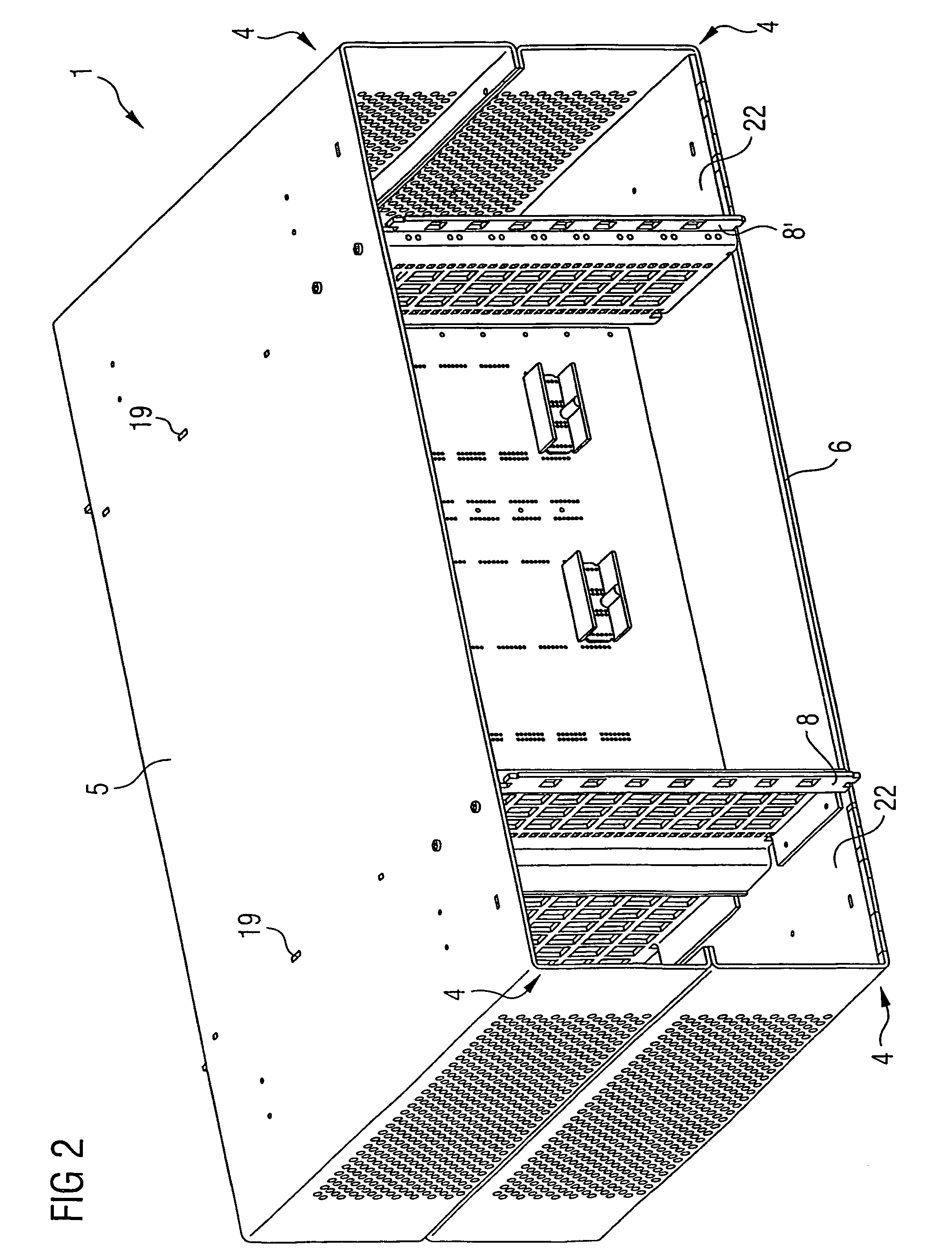
[0035]One exemplary embodiment of the module carrier 1 according to the invention is shown in the three-dimensional representation in FIG. 1 and FIG. 2. In the drawing in FIG. 1 the cover element 5 is removed and the mounting space 2 can be seen. Guiding gratings 7, 7′, 8, 8′ are arranged facing each other in pairs on a base element 6. They form lateral limits of a mounting space 2. An intermediate wall card 3 divides this mounting space into a front section 9 and a rear section 10. During production of the module carrier, in a first stage, the front guiding gratings 7, 7′ are connected to the base element 6 and the cover element 5 by spot welding. Edges folded at right-angles 23 are provided on the cover and base sides of the guiding gratings for this purpos...


PUM


Abstract

Electric or electronic modules may be carried by an electrically shielded module carrier that includes a cover element and a base element enclosing at least one mounting region which is divided into a front section and a rear section by an intermediate wall card. Holding elements for inserted flat modules are laterally provided in each section and include guiding gratings which face each other in pairs and are integrated into an electromagnetic shield. The cover element and the base element are connected to the guiding gratings of the front section in a fixed manner and are detachably connected to the guiding gratings of the rear section.

Description

CROSS REFERENCE TO RELATED APPLICATIONS[0001]This application is based on and hereby claims priority to German Application No. 102 30 704.0 filed on Jul. 8, 2002, the contents of which are hereby incorporated by reference.BACKGROUND OF THE INVENTION[0002]1. Field of the Invention[0003]The invention relates to an electrically shielded module carrier for receiving electric and / or electronic modules, the carrier including a cover element and a base element, with at least one mounting space, which is divided into a front section and a rear section by an intermediate wall card. Holding elements for inserted flat modules are provided laterally in each of these sections.[0004]2. Description of the Related Art[0005]Module carriers serve to receive different electric and electronic units. In many areas of electrical engineering, in particular in the area of communication technology, the problem arises that in the module carrier the mounting space for electronic units has to be protected agai...

Claims


Application Information

Patent Timeline
Patent Type & Authority Patents(United States)
IPC IPC(8): H05K9/00H05K7/14
CPCH05K9/0062
Inventor PLABST, ROLAND
Owner UNIFY GMBH & CO KG
Why Eureka
Try Eureka