Mat assembly for heavy equipment transit and support

a technology for supporting and heavy equipment, applied in the direction of girders, joists, ways, etc., can solve the problems of inability to use iron or steel i-beams for such applications, low torsional rigidity of beams, and high cost, so as to prevent distortion or bending of central webs, increase strength

Inactive Publication Date: 2008-05-13
NEWPARK MATS & INTEGRATED SERVICES
View PDF48 Cites 34 Cited by
  • Summary
  • Abstract
  • Description
  • Claims
  • Application Information

AI Technical Summary

Problems solved by technology

A drawback to I-beams is relatively low torsional (twisting) rigidity.
However, it is not feasible to use iron or steel I-beams for such applications, as they would be far too heavy and too expensive, and further are subject to corrosion.
While it may be possible to form I-beams out of lighter and less expensive materials such as wood, decay is a problem, since the application is often in a wet, soft terrain environment.
Wooden members therefore often turn out to be single-use members due to rotting, breaking and splintering from high loads, etc.

Method used


Image

  • Mat assembly for heavy equipment transit and support
  • Mat assembly for heavy equipment transit and support
  • Mat assembly for heavy equipment transit and support

Examples


Embodiment Construction

[0019]While the present invention lends itself to various embodiments, as will be recognized by those having ordinary skill in this art field, with reference to the drawings some presently preferred embodiments will be described.

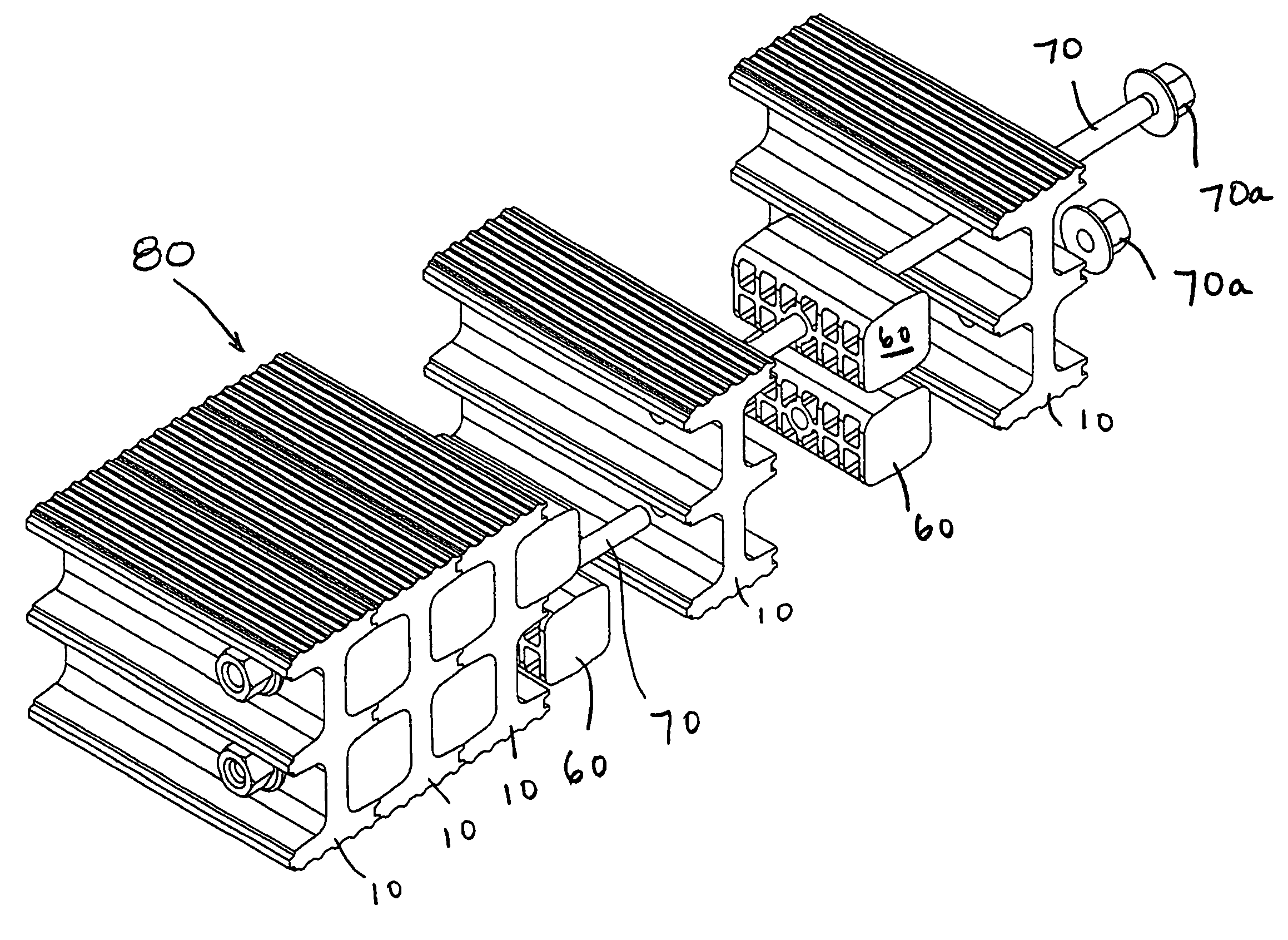
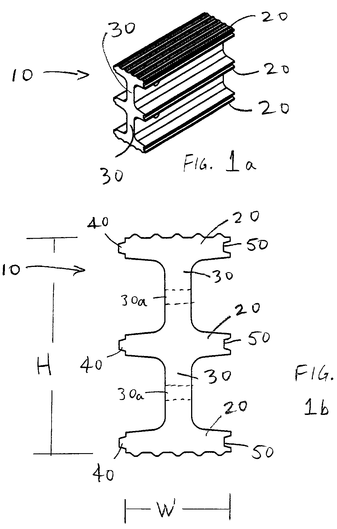
[0020]FIGS. 1a and 1b are perspective and cross section views of one embodiment of the I-beam structural member of the present invention. In this embodiment, beam 10 comprises three spaced apart flanges 20 connected by webs 30. In effect, a “double I-beam” is formed. Each edge of flanges 20 comprise a recurring geometric profile adapted to mesh together with an adjacent I-beam, and in the preferred embodiment is either a tongue 40 or groove 50 profile. Preferably, each flange 20 has a tongue 40 on one edge and a groove 50 on its other edge. Further, each flange on a single beam has its tongue and groove on the same side as the tongues and grooves of the other flanges on the same beam. Said another way, all tongues 40 are on the same side of beam 10, and all ...


PUM

PropertyMeasurementUnit
tensile strengthsaaaaaaaaaa
thicknessaaaaaaaaaa
thicknessaaaaaaaaaa

Abstract

A mat assembly particularly suited for heavy equipment transit and support, such as roadway construction and the like. The mat assembly is made up of a number of structural members preferably having a “double I-beam” cross-sectional shape. Each I-beam has spaced apart flanges with edges preferably formed in tongue and groove profiles. When butted together, the tongue and grooves of adjacent I-beams mesh. Filler blocks are disposed in the cavities between the webs of the I-beams. Tension members extending through the webs and filler blocks tie multiple I-beams together to form the mat assembly. Preferably, both the I-beams and filler blocks are formed of a plastic material, via extrusion or other molding methods. The resulting mat is capable of bearing very high loads yet is decay resistant.

Description

BACKGROUND[0001]1. Field of Art[0002]This invention relates to structural members and assemblies thereof, used in various fabrication purposes. With more particularity, this invention relates to structural members preferably (but not exclusively) formed from plastic or composite materials, and a support mat assembly fabricated therefrom.[0003]2. Related Art[0004]Structural members of many different varieties are old in the art. In particular, so-called “I-beams,” bearing that name because the cross-sectional shape of the structural member resembles the letter “I,” have been used for many, many years in building fabrication and the like. Such I-beams were primarily made of iron or steel. The typical I-beam, well known in the art, has two spaced-apart parallel flanges connected by a central web. A key advantage to use of an I-beam, as opposed to a solid beam having the same outer dimensions, is that the I-beam is much more structurally “efficient.” By that is meant that a tremendously...

Claims


Application Information

Patent Timeline
Patent Type & Authority Patents(United States)
IPC IPC(8): E04B5/10E04B5/02E01C9/08
CPCE01C9/086
Inventor ROGERS, MELISSA B.
Owner NEWPARK MATS & INTEGRATED SERVICES
Why Eureka
Try Eureka