Extended flashback annulus in a gas turbine combustor

a gas turbine and flashback annulus technology, applied in the direction of machines/engines, mechanical equipment, lighting and heating apparatus, etc., can solve the problems of high-temperature combustion that produces high levels of unwanted nox emissions, and damage to components that mix fuel with air

Active Publication Date: 2008-05-13
SIEMENS ENERGY INC
View PDF24 Cites 27 Cited by
  • Summary
  • Abstract
  • Description
  • Claims
  • Application Information

AI Technical Summary

Problems solved by technology

Combustion of over-rich pockets of fuel and air leads to high-temperature combustion that produces high levels of unwanted NOx emissions.
Although a stable but lean mixture is desired for fuel efficiency and for environmentally acceptable emissions, a flashback may occur at times more frequently with a lean mixture, and particularly during unstable operation.
Less frequently, the flame may flash back into a fuel / air mixing apparatus, damaging components that mix the fuel with the air.

Method used


Image

  • Extended flashback annulus in a gas turbine combustor
  • Extended flashback annulus in a gas turbine combustor
  • Extended flashback annulus in a gas turbine combustor

Examples


Embodiment Construction

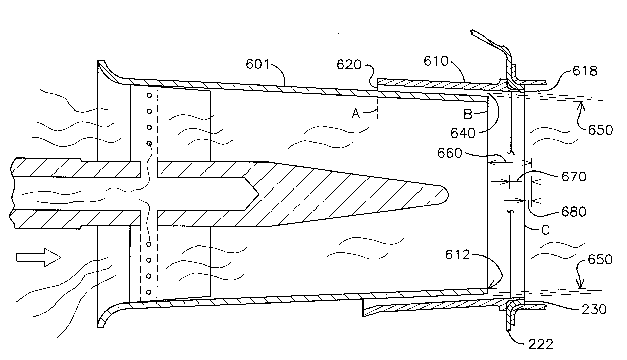
[0018]The invention relates to formation and utilization of an improved channel, referred to herein specifically as a flashback annulus, through which flows air that surrounds an inner flow of fuel / air formed by swirler-type fuel / air mixing devices. Embodiments providing the improved channel as described and claimed herein provides a more robust surrounding air flow that better protects against occurrences of flashback by being more substantial and persisting in a protective form a greater distance into the combustion chamber. While the embodiments described below and depicted in the appended figures are illustrative of some forms of the invention, the full scope of the invention is not meant to be limited by these embodiments.

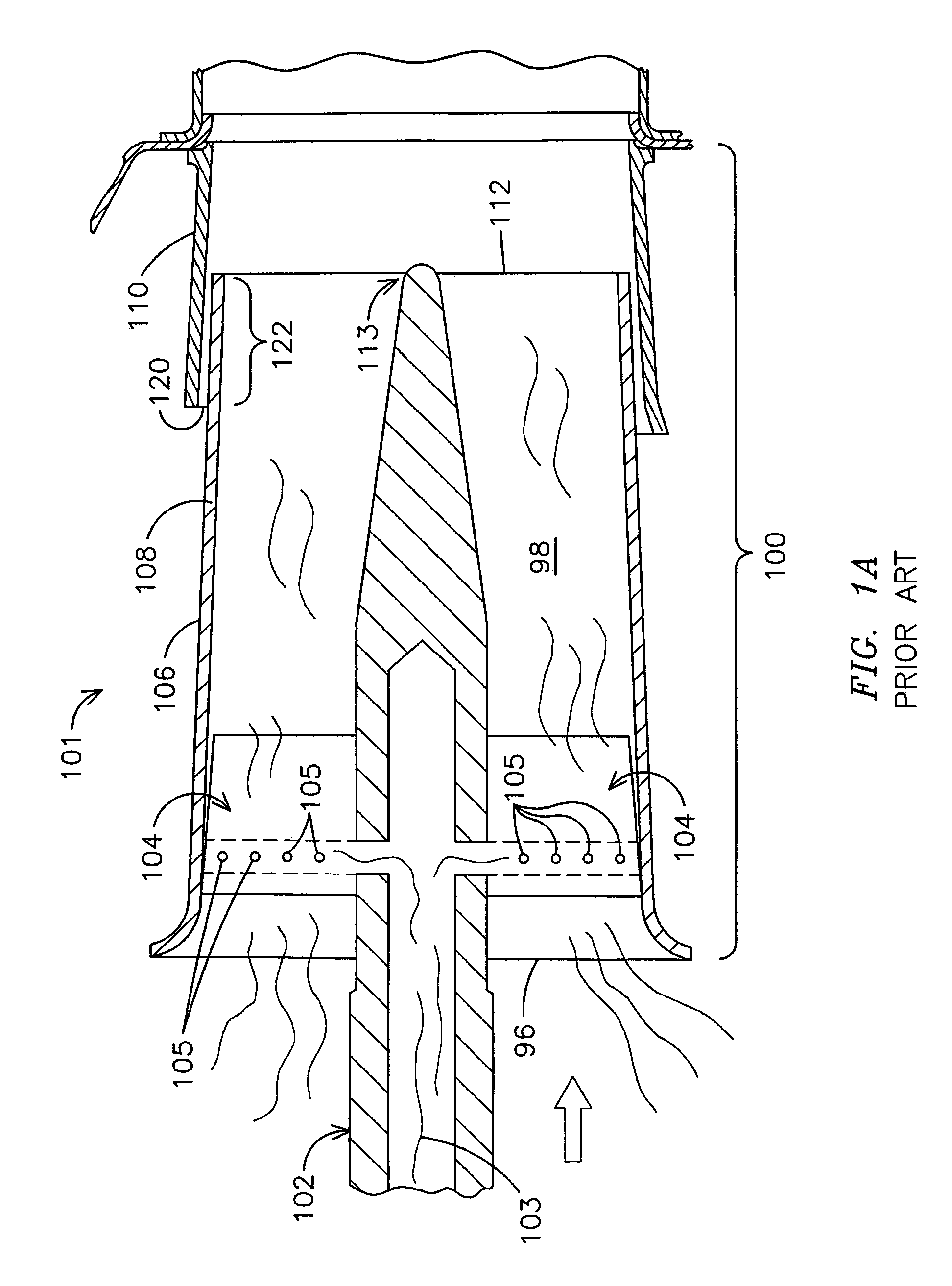
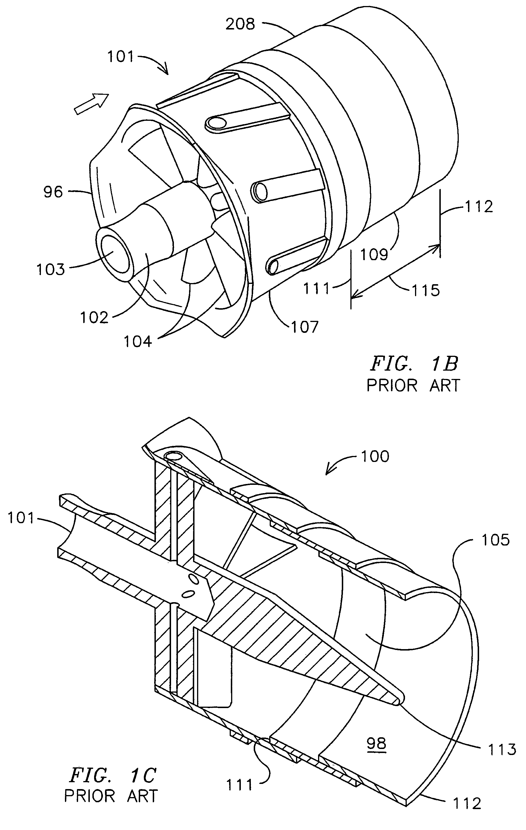
[0019]FIG. 1A provides a side cross-sectional view of a prior art main swirler assembly 100 comprising an inner body 101 and a flashback annulus 110, both of which are generally cylindrical. The direction of air flow during operation is indicated by an arrow. ...


PUM


Abstract

An extended flashback annulus (520) is formed between an exterior surface (506) of a shroud or casing (508) associated with a main swirler assembly inner body (500) or other fuel / air mixing device and the inner surface (514) of an annulus casting (510) which are in operational relationship with one another in a gas turbine combustor assembly. The extended flashback annulus (520) is capable of forming an extended protective cylindrical air barrier (550) that extends farther into the combustion zone, this barrier being more robust and providing for the reduction or prevention of flashback to the baseplate and other heat-susceptible upstream components.

Description

FIELD OF THE INVENTION[0001]This invention relates to a combustion products generator, such as a gas turbine, having swirler-type fuel / air mixing apparatuses in an operational orientation with annulus casting housings so as to form a robust flow of air around the fuel / air mixture generated by each apparatus. This is effective in reducing the occurrence of undesired flashbacks.BACKGROUND OF THE INVENTION[0002]Combustion engines are machines that convert chemical energy stored in fuel into mechanical energy useful for generating electricity, producing thrust, or otherwise doing work. These engines typically include several cooperative sections that contribute in some way to this energy conversion process. In gas turbine engines, air discharged from a compressor section and fuel introduced from a fuel supply are mixed together and burned in a combustion section. The products of combustion are harnessed and directed through a turbine section, where they expand and turn a central rotor.[...

Claims


Application Information

Patent Timeline
Patent Type & Authority Patents(United States)
IPC IPC(8): F23R3/42F23R3/18
CPCF23R3/286
Inventor CAI, WEIDONG
Owner SIEMENS ENERGY INC
Why Eureka
Try Eureka