
One-piece friction body with a support and a friction pad disposed thereon and method of its manufacture

a friction body and support technology, applied in the direction of friction linings, brake types, other chemical processes, etc., can solve the problems of friction pads not possessing the heat resistance required, friction pads may bulge between the “rivets", laborious and expensive riveting, etc., to achieve the effect of enhancing the strength properties of the friction body and increasing shear strength

Inactive Publication Date: 2008-05-13
REX IND PROD GRAF VON REX
View PDF9 Cites 15 Cited by
  • Summary
  • Abstract
  • Description
  • Claims
  • Application Information

AI Technical Summary

Benefits of technology

[0009]It is now an object of the present invention to provide a one-piece friction body of the type as described above, in which the friction pad and the support are manufactured and joined to one another in a single operation, whereby it is easily possible to impart to the friction pad on the one hand and to the support on the other hand the properties required for the friction pad and the support, respectively, to fulfil their functions, and to nevertheless attain a homogeneous joint of these parts. It is another object to provide such a one-piece friction body which has at least two portions having different friction properties and / or mechanical properties and thus has, on one or both friction surfaces, portions having different friction properties. In this connection, it should be possible to also superpose the friction surfaces in the form of a plurality of layers having different layer thicknesses or, however, to design the friction surfaces in the form of segments or fields of any desired shape which are arranged side by side and have respectively different friction properties, so that one succeeds in adjusting the friction behavior exactly to the technical requirements for the intended use. In this connection, it must be ensured in all cases that the friction pad is joined to the support, or the friction pads are joined to one another and to the support, in such a way that there is a distinct increase in shear strength between the individual parts or layers, thus enhancing the strength properties of the friction body.

Problems solved by technology

The also employed two-component adhesives do not possess the heat resistance required in the use of the friction bodies.
Joining the friction pads to the support by riveting is laborious and expensive and only offers a pointwise fixing of the friction pad, so that the latter may bulge between the “rivets”.
Another large drawback lies in the high cost of manufacture of the metal supports, especially when these supports have inner or outer teeth which must have a very high fitting accuracy.
Last, problems arise from the different thermal expansion of the metallic support and the friction pad due to distortion of the friction pads and their becoming detached from the support.
The joining of these individual parts to one another, and to the required support consisting, for example, of steel, not only is expensive due to providing this metallic support and the required adhesive but also cannot be satisfactory in view of the requisite joining of the parts of the friction body to one another and to the support.
The friction bodies known from this state of the art which comprise a support and at least one friction pad disposed thereon cannot be satisfactory in so far as the friction pad and the support are manufactured separately and in a manner involving high cost and must subsequently be joined, for example by bonding with an adhesive or by riveting, which methods of attachment often do not offer the strength that is required in practice, so that there may occur deformation, or possibly even detachment, of the friction pad disposed on the support.

Method used


Image

  • One-piece friction body with a support and a friction pad disposed thereon and method of its manufacture
  • One-piece friction body with a support and a friction pad disposed thereon and method of its manufacture

Examples


Embodiment Construction

[0015]According to a preferred embodiment of this friction body, the friction materials of the at least one friction pad and the support are joined to one another integrally and positive-locking by needling of the reinforcing fibers contained in the respective friction materials, prior to curing of the friction materials under heat and pressure in a pressing mold corresponding to the friction body to be produced, from the outer surfaces of the friction body.

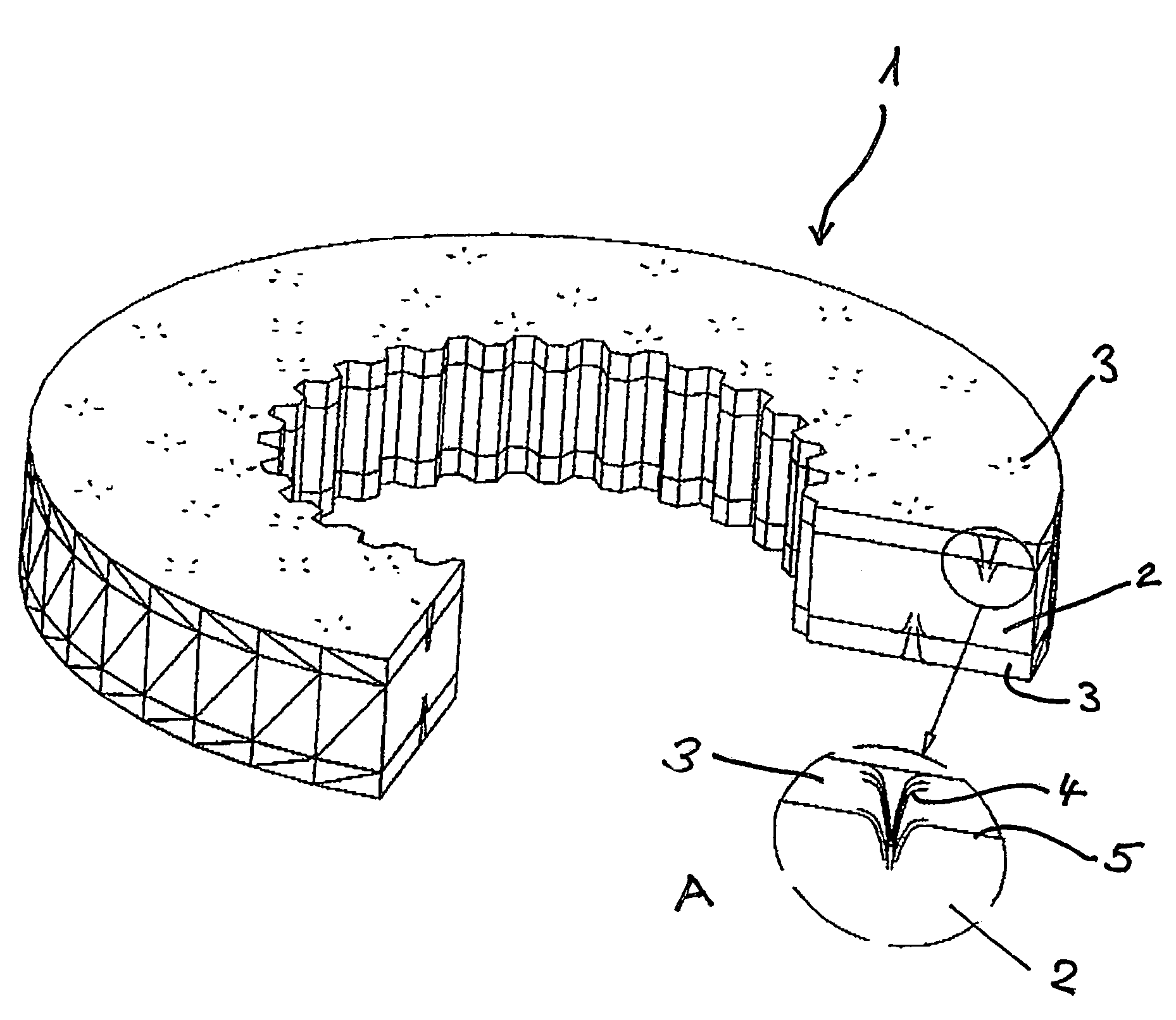
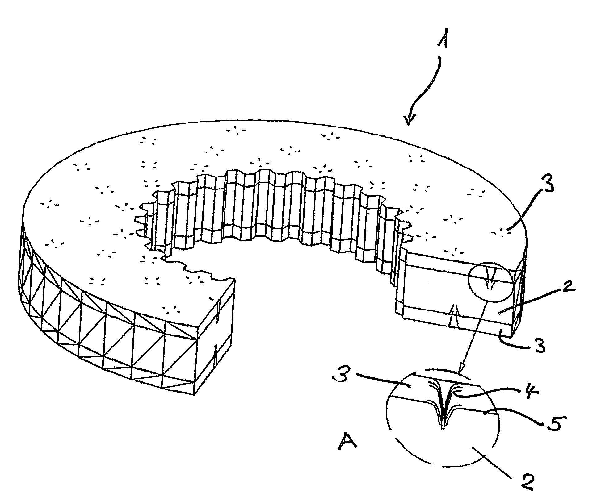
[0016]As shown in the drawing, the one-piece friction body (1) includes a support (2) and two friction pads (3) disposed thereon. As can be seen from enlarged part A of the drawing, the friction pad (3) is joined to the support (2) integrally and positive-locking by means of the reinforcing fibers (4) penetrating the boundary layer (5) between the support (2) and the friction pad (3).

[0017]As a result of the needling according to the invention of the friction materials for the support and the at least one friction pad disposed th...


PUM


Abstract

There is described a one-piece friction body having a support and at least one friction pad disposed thereon, based on friction materials containing reinforcing fibers, thermoset binders and customary additives, in which the at least one friction pad is joined to the support integrally and positive-locking by means of reinforcing fibers penetrating the boundary layer between the support and the friction pad. There is further described a method of manufacturing this friction body, comprising the steps of bonding together the friction materials containing reinforcing fibers, thermosetting binders and customary additives for the support and the at least one friction pad in the desired shape and arrangement, needling the reinforcing fibers contained in the friction materials of the composite in such manner that at least the reinforcing fibers of the friction material of the at least one friction pad penetrate at least in part the friction material of the support and of the other friction pad, respectively, and curing the needled intermediate under heat and pressure in a pressing mold corresponding to the friction body to be manufactured.

Description

FIELD OF THE INVENTION[0001]The invention relates to a one-piece friction body with a support and at least one friction pad disposed thereon, based on friction materials containing reinforcing fibers, thermoset binders and customary additives, as well as a method of its manufacture.BACKGROUND[0002]Friction bodies which contain reinforcing fibers, lubricants, abrasives, inorganic materials and fillers in a binder matrix cured under the action of heat and pressure are widely used in various technical fields, in particular as brake pads, clutch pads, or friction pads. These friction bodies generally comprise a support, or a support plate, made of metal or synthetic material and at least one friction pad disposed thereon. The joining of the friction pad and the support is usually accomplished by riveting or bonding. The metallic support may be present in the form of a plate or hub with inner or outer teeth, or, however, also in the form of a brake block support.[0003]The friction pad no...

Claims


Application Information

Patent Timeline
IPC IPC(8): F16D65/04C08J5/14F16D69/04C09K3/14F16D65/092F16D69/02
CPCF16D65/092F16D69/026F16D2069/0483
Inventor VOLLWEITER, HEINRICH
Owner REX IND PROD GRAF VON REX
Learn More