Liquid supplying member, method of manufacturing the same, and liquid ejection apparatus incorporating the same

a technology of liquid supplying member and liquid ejection apparatus, which is applied in the direction of printing, etc., can solve the problems of increasing the size of the apparatus, the inability to increase the flexural rigidity, and the increase of the cost of manufacture, so as to improve the durability and the elasticity of the liquid supplying member.

Inactive Publication Date: 2008-05-13
SEIKO EPSON CORP
View PDF23 Cites 15 Cited by
  • Summary
  • Abstract
  • Description
  • Claims
  • Application Information

AI Technical Summary

Benefits of technology

[0009]It is therefore an object of the present invention to provide a liquid supplying member in use for the liquid ejection apparatus in which a flexural rigidity of the ink supplying tube is reduced, and satisfactory anti-water permeability and gas barrier properties are realized at low cost, and to provide a liquid ejection apparatus provide with the liquid supplying tube.
[0010]It is also an object of the invention to provide a liquid supplying member in which the liquid ejection apparatus body can be made compact and the attaching operation of the liquid supplying member can be facilitated.

Problems solved by technology

In any case, the result is a further size increase of the apparatus.
Where a multi-layer construction is introduced into the tube annular in cross section, it is basically unavoidable to increase the flexural rigidity.
This results in increase of cost to manufacture.

Method used


Image

  • Liquid supplying member, method of manufacturing the same, and liquid ejection apparatus incorporating the same
  • Liquid supplying member, method of manufacturing the same, and liquid ejection apparatus incorporating the same
  • Liquid supplying member, method of manufacturing the same, and liquid ejection apparatus incorporating the same

Examples


first embodiment

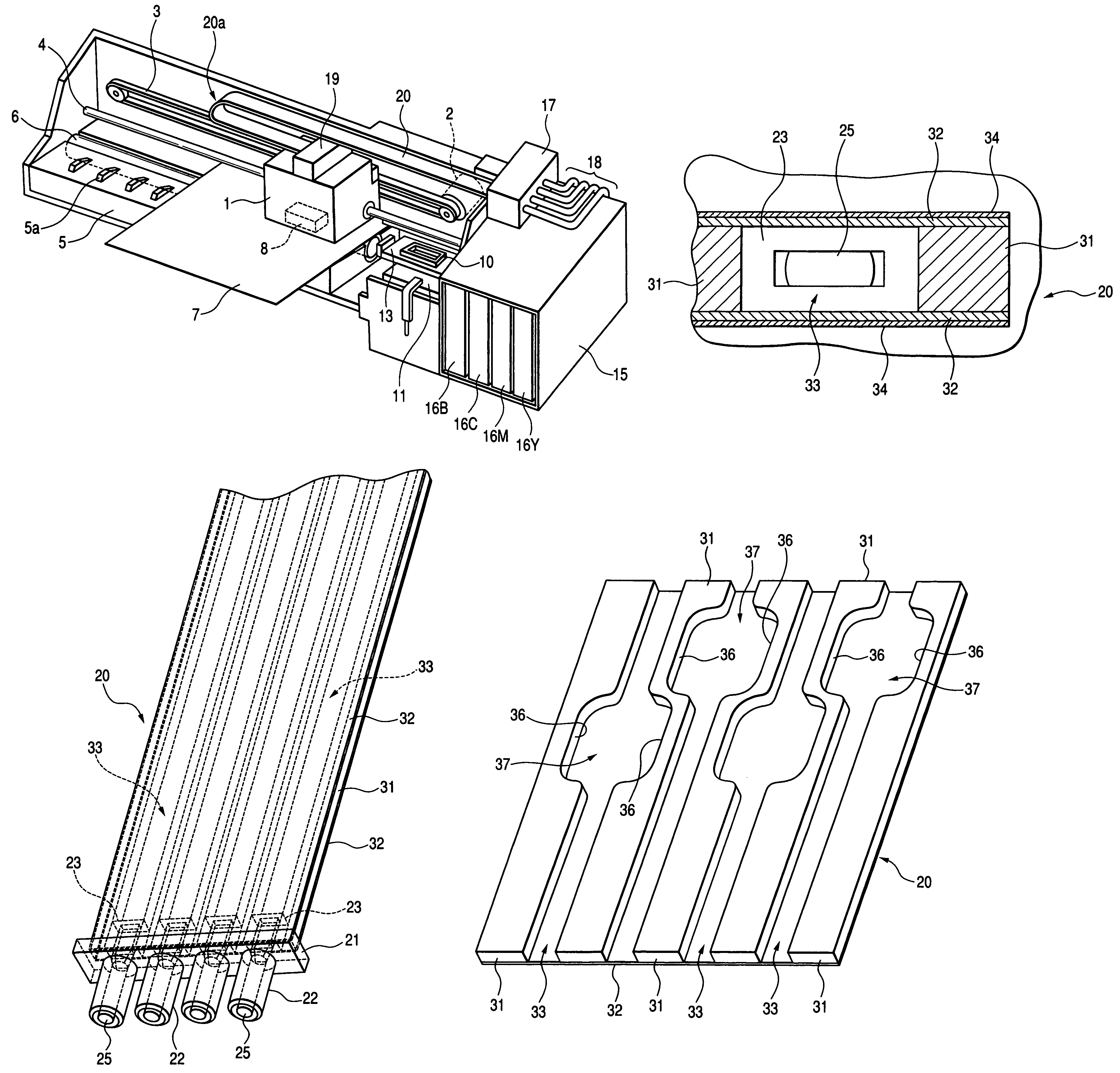
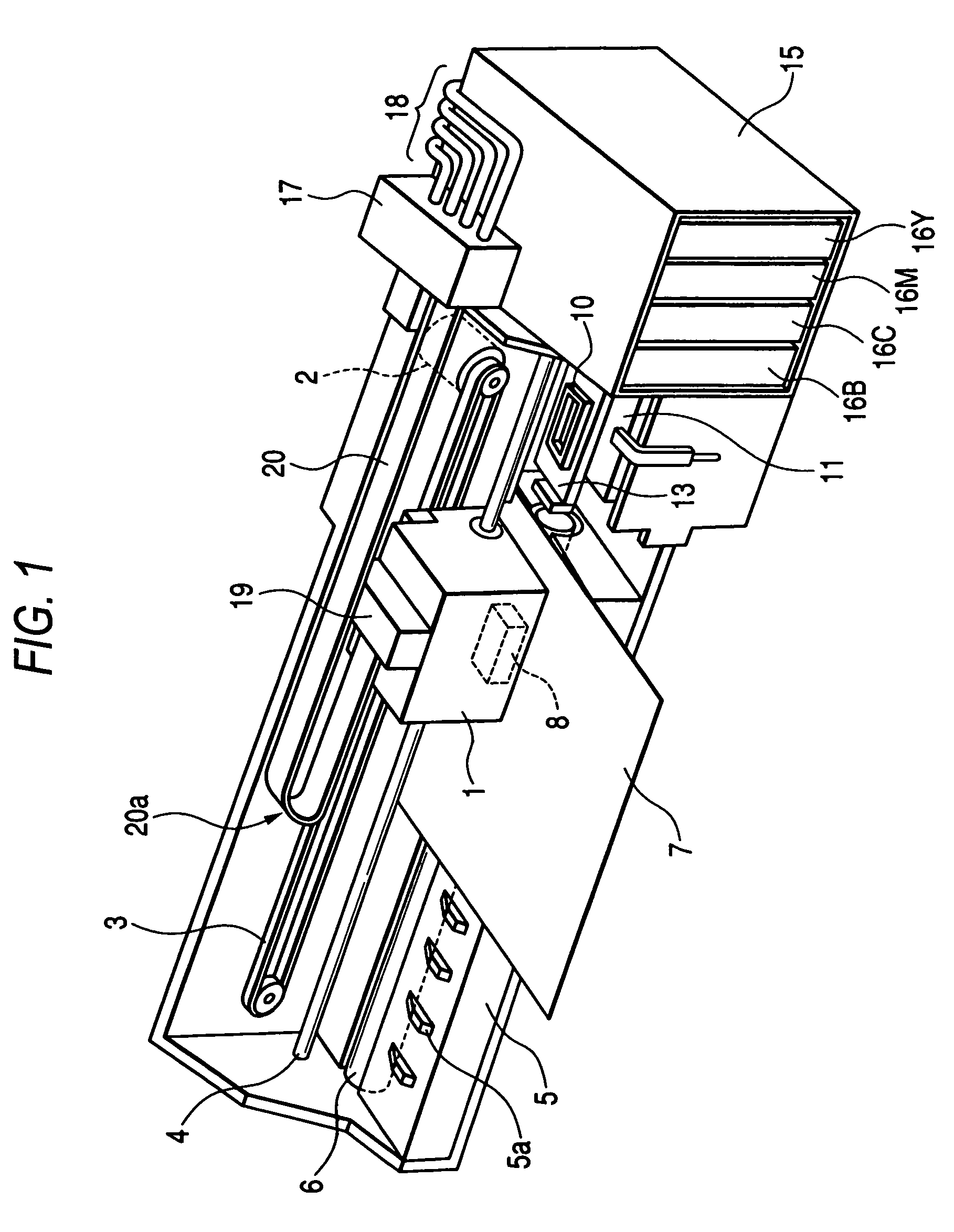
[0107]FIG. 1 shows an ink jet recording apparatus as an example of a liquid ejection apparatus incorporating a liquid supplying member according to the invention. In the recording apparatus, a carriage 1 is reciprocatively moved in the primary scanning direction which extends along a longitudinal direction of a sheet feeder 5, while being guided by a guide member 4 with the aid of a timing belt 3 driven by a carriage motor 2.

[0108]The sheet feeder 5 is provided with a sheet feeding roller 6. A recording sheet 7, nipped between the sheet feeding roller 6 and a follower roller (not shown), is transported by rotation of the sheet feeding roller 6 in a secondary scanning direction orthogonal to the primary scanning direction. A number of protrusions 5a are intermittently arrayed in the longitudinal direction on the upper face of the sheet feeder 5. The recording sheet 7 is transported along the top faces of the thus arrayed protrusions 5a.

[0109]An ink jet recording head 8, as indicated...

second embodiment

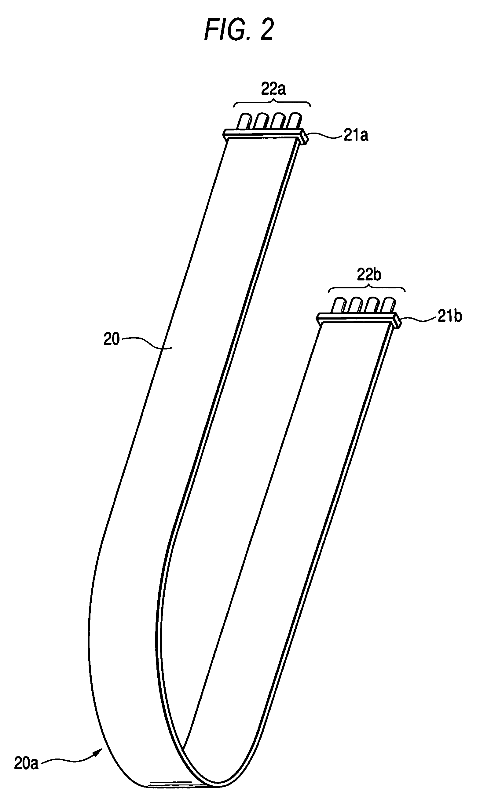
[0137]As in the second embodiment, since a single ink supplying passage 33 is provided in a single ink supplying tube 20, four independent tubes are to be incorporated in the apparatus shown in FIG. 1.

[0138]Although it is not explicitly shown in these figures, it is preferable to form thin films 34 on the outer faces of the film member 32 by aluminum lamination process, as in the case shown in FIG. 6.

[0139]As shown in FIGS. 11 and 12, an ink jet recording apparatus 110 is provided with: a carriage 142 which reciprocally travels so as to straddle a recorded object; a recording head 144 which is mounted on the carriage 142 and subjects the object to recording, writing, or printing by ejecting a plurality of colors of ink to the object; a plurality of cartridges 145 which contains different colors of ink therein; and a liquid supplying member 200.

[0140]The carriage 142 is reciprocally moved along a guide shaft 148 by an unillustrated motor. The cartridges 145 are fixed not to the carri...

fourth embodiment

[0146]As shown in FIG. 13, the liquid supplying member 200 comprises a base member 210 made of plastic material, and an elongated plate member 220 joined to one face 210a of the base member 210 by, e.g., adhesion or welding. While being joined to the base member 210, the elongated plate member 220 has flexibility.

[0147]The base member 210 is formed with a plurality of elongated ridges 211 defining a plurality of individual grooves 212 each having rectangular cross section and arranged in a width direction of the base member 210. Open side of the grooves 212 are covered with the elongated plate member 112 to form a plurality of individual ink supplying passages.

[0148]Such a structure enables manufacture of the liquid supplying member 200 by injecting plastic material (e.g., a thermoplastic elastomer) into a mold, to thereby mold the base member 210. In this case, the base member 210 can be formed into a complicated geometry, and manufacturing costs can be reduced. In addition to the...


PUM


Abstract

In a liquid supplying member, for supplying liquid from a liquid container to a liquid ejection head which are provided in a liquid ejection apparatus, a plurality of elastic members, each of which is elongated in a first direction so as to have a first face and a second face, are arrayed in a second direction perpendicular to the first direction. A first film member is joined to the first face of each of the elastic members. A second film member is joined to the second face of each of the elastic members, such that a passage, through which the liquid is supplied from the liquid container to the liquid ejection head, extending in the first direction is hermetically defined between the adjacent elastic members by inner faces of the first film member and the second film member.

Description

[0001]This is a continuation-in-part application of U.S. patent application Ser. No. 10 / 830,091 filed on Apr. 23, 2004 now U.S. Pat. No. 7,273,271, which is a continuation-in-part application of U.S. patent application Ser. No. 10 / 374,526 filed on Feb. 27, 2003 now abandoned. Applications Ser. Nos. 10 / 830,091 and 10 / 374,526 are incorporated herein by reference in their entirety, and so are all of the Japanese patent applications from which priority is claimed, namely: 2002-053905 filed Feb. 28, 2002; 2003-026154 filed Feb. 3, 2003; 2003-120528 filed Apr. 24, 2003; 2003-198792 filed Jul. 17, 2003; 2003-198795 filed Jul. 17, 2003; 2003-198796 filed Jul. 17, 2003; 2003-198798 filed Jul. 17, 2003; 2003-199070 filed Jul. 18, 2003; and 2003-199882 filed Jul. 22, 2003.BACKGROUND OF THE INVENTION[0002]The invention relates to a liquid supplying member for supplying liquid contained in a liquid cartridge to a liquid ejection apparatus for effecting recording or printing operation. The invent...

Claims


Application Information

Patent Timeline
Patent Type & Authority Patents(United States)
IPC IPC(8): B41J2/175
CPCB41J2/175B41J2/17509B41J2/17523
Inventor SHIHO, AKIHIKOKUMAGAI, TOSHIOKOBAYASHI, ATSUSHITAKEMURA, MASANORIMATSUMOTO, HITOSHIKIMURA, HITOTOSHI
Owner SEIKO EPSON CORP
Why Eureka
Try Eureka