Lamp body for a fluorescent lamp

a fluorescent lamp and lamp body technology, applied in the direction of elongated light sources, low-pressure discharge lamps, lighting and heating apparatus, etc., can solve the problems of low luminance and inefficiency of fluorescent lamps, and achieve the effect of improving the luminance of fluorescent lamps

Inactive Publication Date: 2008-05-13
GAYA LIMITED
View PDF5 Cites 41 Cited by
  • Summary
  • Abstract
  • Description
  • Claims
  • Application Information

AI Technical Summary

Benefits of technology

[0006]The primary objective of the present invention is to provide a lamp body for a fluorescent lamp to improve a luminance of the fluorescent lamp.
[0007]The lamp body has an inner surface. The inner surface is separated into multiple sections. The multiple sections are arranged on the inner surface of the lamp body and include at least one coated section coated with fluorescent powders and at least one non-coated section being naked and kept free from fluorescent powders. Thus, when ultraviolet rays collide into the fluorescent powders and generate visible lights, the at least one non-coated section allows the visible lights to directly pass through the lamp body to improve a luminance of the fluorescent lamp.

Problems solved by technology

However, the inner surface of the lamp body of the conventional fluorescent lamp is wholly coated with the fluorescent powders, so part of the visible lights inside the lamp body is reflected by the fluorescent powders and cannot pass through the lamp body.
Because part of the visible lights cannot pass through the lamp body, a luminance of the fluorescent lamp is lowered and inefficient.

Method used


Image

  • Lamp body for a fluorescent lamp
  • Lamp body for a fluorescent lamp
  • Lamp body for a fluorescent lamp

Examples


first embodiment

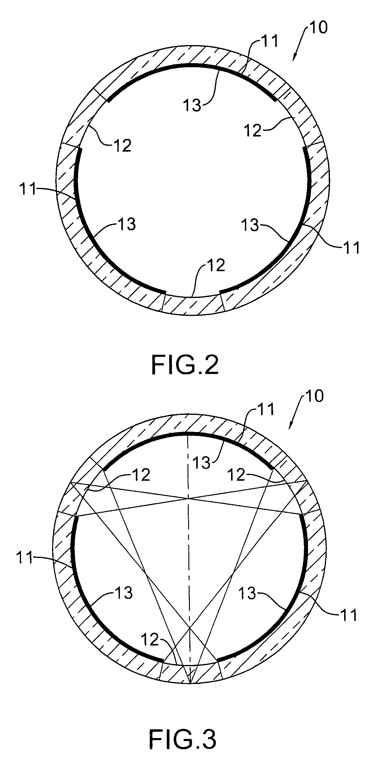
[0018]With further reference to FIGS. 2 and 3, in the sections of the inner surface of the lamp body (10), the sections are arranged circularly and consecutively on the inner surface of the lamp body, respectively are an elongated curved area extending axially along the lamp body (10) and may include three coated sections (11) and three non-coated sections (12). The coated sections (11) are arranged on the inner surface of the lamp body (10) at intervals. Because each of the sections is an elongated curved area, each of the coated sections is analogous to a concave mirror and has an effect to converge the visible lights that are reflected by the coated section. The non-coated sections (12) are arranged respectively between the coated sections (11) and each of the non-coated sections (12) diametrically faces one of the coated sections (11). Thus, the visible lights converged by the coated sections (11) are more likely to pass out of the lamp body (10) through a corresponding one of t...

second embodiment

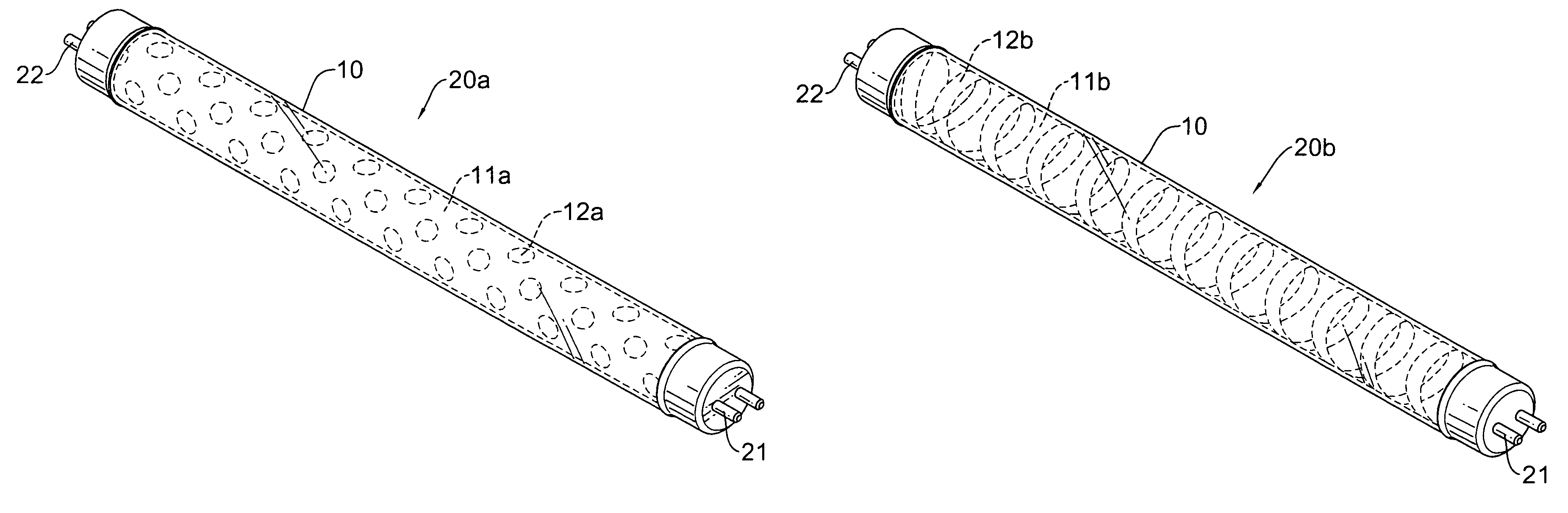
[0019]With further reference to FIG. 4, in the sections, the sections include multiple non-coated sections (12a) and a single coated section (11a). The non-coated sections (12a) respectively are a round curved area and are distributed on the inner surface of the lamp body (10). The coated section (11a) is arranged on the inner surface of the lamp body (10) exclusive of the non-coated sections (12a).

third embodiment

[0020]With further reference to FIG. 5, in the sections, the sections are arranged spirally and consecutively on the inner surface of the lamp body (10) and respectively are an elongated spiral area.

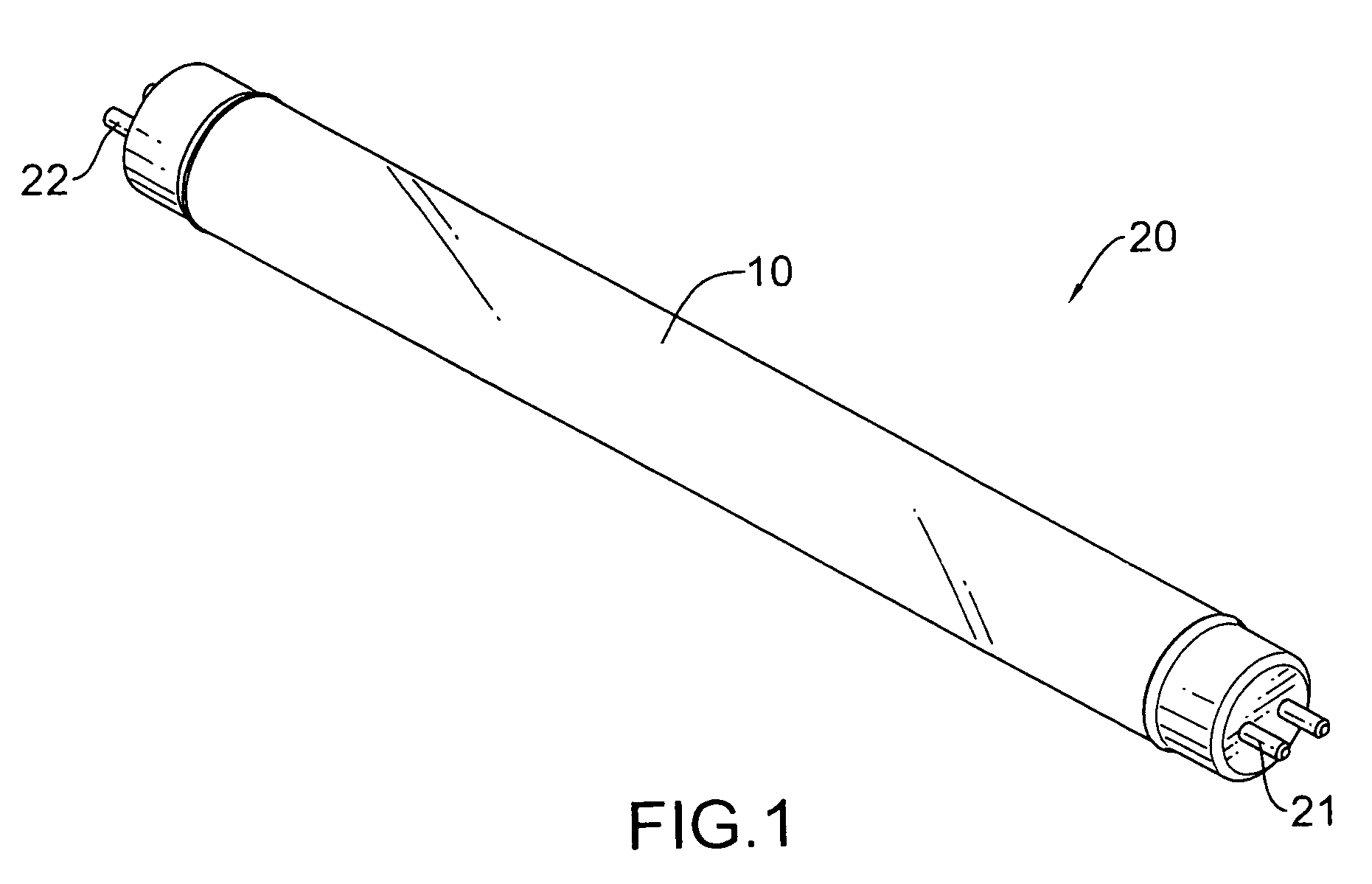
[0021]The positive electrode (21) and the negative electrode (22) are mounted respectively at the two ends of the lamp body (10). When the positive electrode (21) and the negative electrode (22) are connected to a power source and a high voltage are imposed between the positive electrode (21) and the negative electrode (22), the mercury in the lamp body (10) is vaporized and the negative electrode (22) emits electrons to the positive electrode (21). The electrons collide with gas molecules of the vaporized mercury to generate ultraviolet rays. When the ultraviolet rays collide into the fluorescent powders (13) coated on the at least one coated section (11, 11a, 11b), the ultraviolet rays are transformed into visible lights.

[0022]With well proportioning the fluorescent powders (13) on the...


PUM


Abstract

A lamp body for a fluorescent lamp has multiple sections arranged on an inner surface of the lamp body. The sections include at least one coated section coated with fluorescent powders and at least one non-coated section being naked and kept free from fluorescent powders. The fluorescent powders generate visible lights when colliding with ultraviolet rays. The visible lights can directly pass out of the lamp body through the at least one non-coated section to form a light source and improve a luminance of the fluorescent lamp.

Description

BACKGROUND OF THE INVENTION[0001]1. Field of the Invention[0002]The present invention relates to a lamp body for a fluorescent lamp, and more particularly to the lamp body that can improve the luminance ratio of the fluorescent lamp.[0003]2. Description of Related Art[0004]A conventional fluorescent lamp has a lamp body, a positive electrode and a negative electrode. The lamp body is filled with mercury and inert gas and has two ends and an inner surface. The inner surface of the lamp body is coated with fluorescent powders. The positive electrode and the negative electrode are mounted respectively at the two ends of the lamp body. When the positive electrode and the negative electrode of the fluorescent lamps are connected to a power source and a high voltage are imposed between the positive electrode and the negative electrode, the mercury is vaporized and the negative electrode emits electrons to the positive electrode. The electrons collide with gas molecules of the vaporized me...

Claims


Application Information

Patent Timeline
Patent Type & Authority Patents(United States)
IPC IPC(8): F21V9/16F21Y103/00
CPCH01J61/42H01J61/70
Inventor CHAN, CHENG-RON
Owner GAYA LIMITED
Why Eureka
Try Eureka