
Lighting and/or signalling device with light emitting diodes for motor vehicles

a technology of light-emitting diodes and signalling devices, which is applied in semiconductor devices, light-emitting devices, lighting and heating apparatus, etc., can solve the problems of concentrating heat further, and reducing the efficiency of lighting

Inactive Publication Date: 2008-05-13
VALEO VISION SA
View PDF7 Cites 6 Cited by
  • Summary
  • Abstract
  • Description
  • Claims
  • Application Information

AI Technical Summary

Benefits of technology

This solution effectively dissipates heat, reduces the weight and cost of the movable plate, and prevents overheating of the protective lens, while maintaining efficient cooling and orientation of the light source, thus addressing the drawbacks of conventional systems.

Problems solved by technology

However, they have the drawback of emitting a high level of heat locally.
For example, in the case of a halogen lamp, the filament of the lamp has a temperature of around 3,000° C., the glass balloon of the bulb has a temperature above 400° C. and the bulb cap has a temperature around 200° C. These lamps also have the drawback of emitting infrared rays.
In addition, if the protective lens is dirty, the lens absorbs these infrared rays instead of transmitting them, which concentrates the heat further.
It is therefore difficult to ventilate the inside of the housing in order to cool it.
However, even if the temperature of a light emitting diode is relatively low compared with the temperature of a conventional lamp and even if the hot spots are distributed in the housing, it is also necessary to cool such a light source.
However, if each light emitting diode must be mounted on the movable mounting plate with the radiator or heat sink, of relatively large size, which is associated with it, then the movable plate becomes heavy and the motor moving it must be powerful.
On the other hand, it is necessary to use one motor for each movable mounting plate, which considerably increases the cost of each device.
In addition, the use of several motors simultaneously causes a problem of slaving the assembly to an initial position.

Method used


Image

  • Lighting and/or signalling device with light emitting diodes for motor vehicles
  • Lighting and/or signalling device with light emitting diodes for motor vehicles

Examples


Embodiment Construction

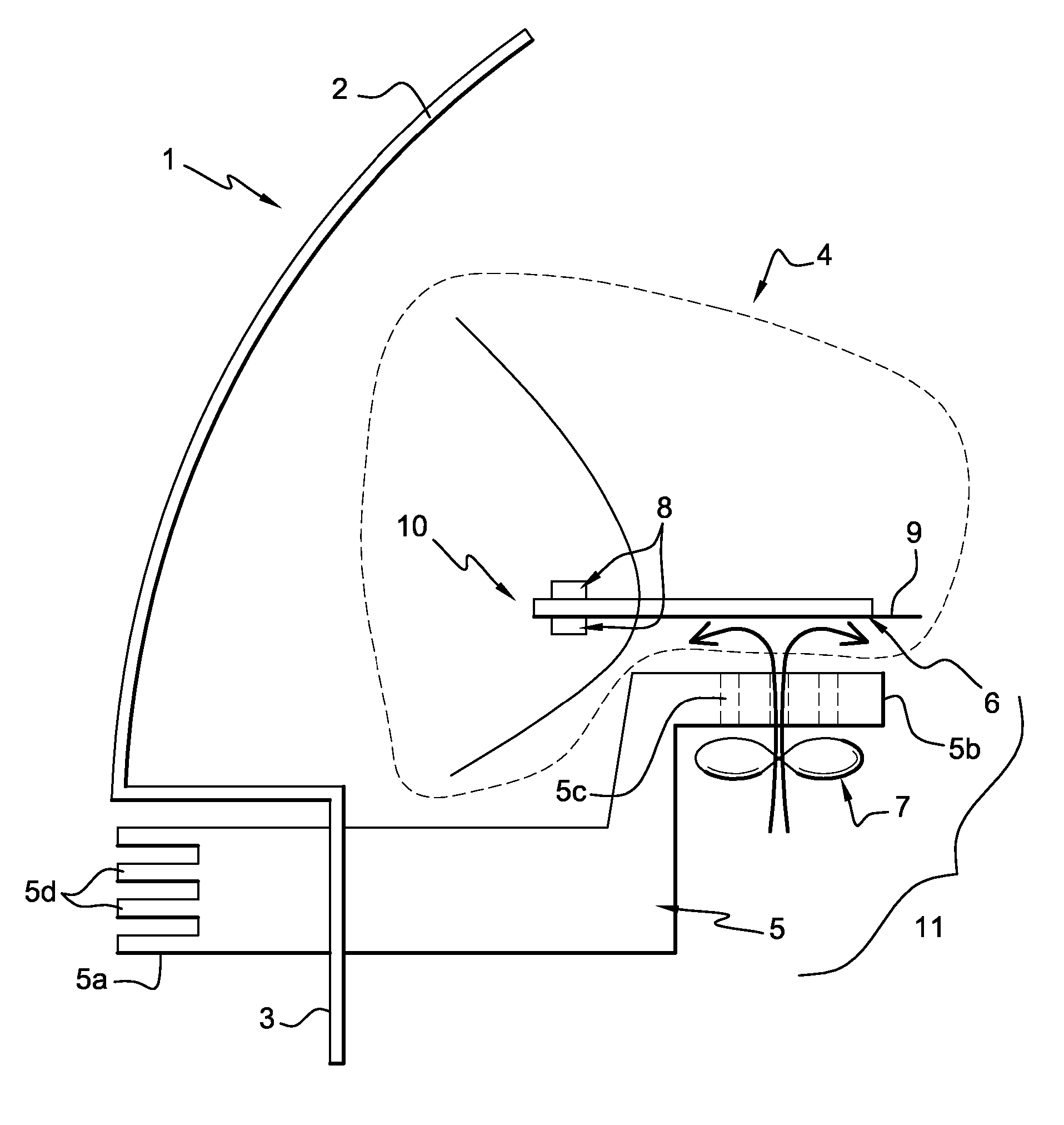
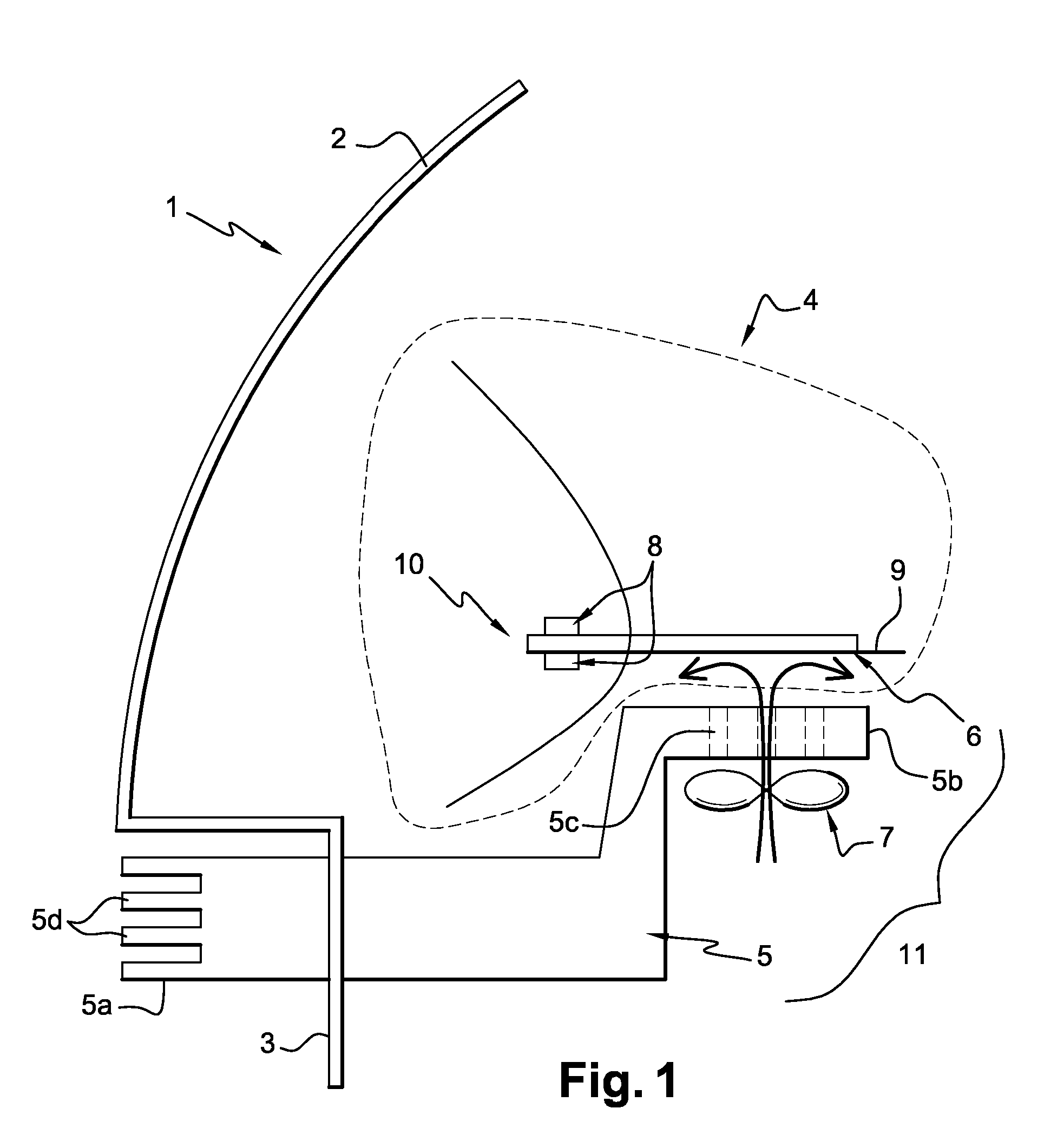
[0033]FIG. 1 depicts an example of a lighting device, also referred to as a headlight, equipped with a light source with light emitting diodes and a cooling device according to the invention. This headlight 1 comprises a moisture-tight housing 3 closed by a protective lens 2 forming an exit face of the housing. This housing 3 is generally produced from a plastic material. The protective lens 2 is mounted sealingly on the housing 3. Inside the housing 3 a light source 10 is produced by means of a plurality of light emitting diodes 8. This light source 10 is able to move inside the housing 3. The orientation of the light source 10 is obtained by virtue of a motor, not shown in the figure.

[0034]The light emitting diodes 8, referred to more simply as LEDs or diodes, can be mounted separately or on the other hand grouped together in the form of modules. The modules can be dispersed inside the housing 3. In the headlight of FIG. 1, the diodes 8 are mounted on a movable plate 9 actuated by...


PUM


Abstract

The invention concerns a lighting and / or signalling device for motor vehicles comprising a housing equipped with a plurality of light emitting diodes mounted on a movable plate, at least one device for cooling the said diodes, comprising at least one first fixed heat sink, at least one second movable heat sink, and at least one means for effecting a forced air convection between the first radiator or heat sink and the second radiator or heat sink.

Description

BACKGROUND OF THE INVENTION[0001]1. Field of the Invention[0002]The invention concerns a lighting or signalling device for motor vehicles in which the light source is produced by means of light emitting diodes. The invention also concerns a motor vehicle comprising such a lighting or signalling device.[0003]The invention finds applications in the automotive field and, in particular, in the field of lighting and signalling for motor vehicles.[0004]2. Description of the Related Art[0005]Generally a motor vehicle comprises at least two lighting devices situated at the front of the vehicle, also called headlights, and signalling devices situated at the front and rear of the vehicle. Each lighting or signalling device comprises a housing closed by a protective lens and equipped firstly with a light source emitting a light beam and secondly optical elements for directing this light beam. Currently, in the majority of lighting or signalling devices, the light source is produced by means of...

Claims


Application Information

Patent Timeline
Patent Type & Authority Patents(United States)
IPC IPC(8): H05K7/20F21W107/10
CPCF21S48/1159F21S48/1742F21S48/325F21S48/328F21S48/335F21V29/90F21V29/004F21V29/02F21V29/73F21V29/76F21S48/34F21Y2101/02F21Y2115/10F21S41/657F21S45/43F21S45/60F21V29/67F21S41/148F21S45/33
Inventor ALBOU, PIERRECHENEVIER, CHRISTOPHEMENSALES, ALEXANDREMOISY, ERIC
Owner VALEO VISION SA
Learn More